Operating and functional elements – Karcher KM 150-500 D 4-r�drig User Manual
Page 19
-
3
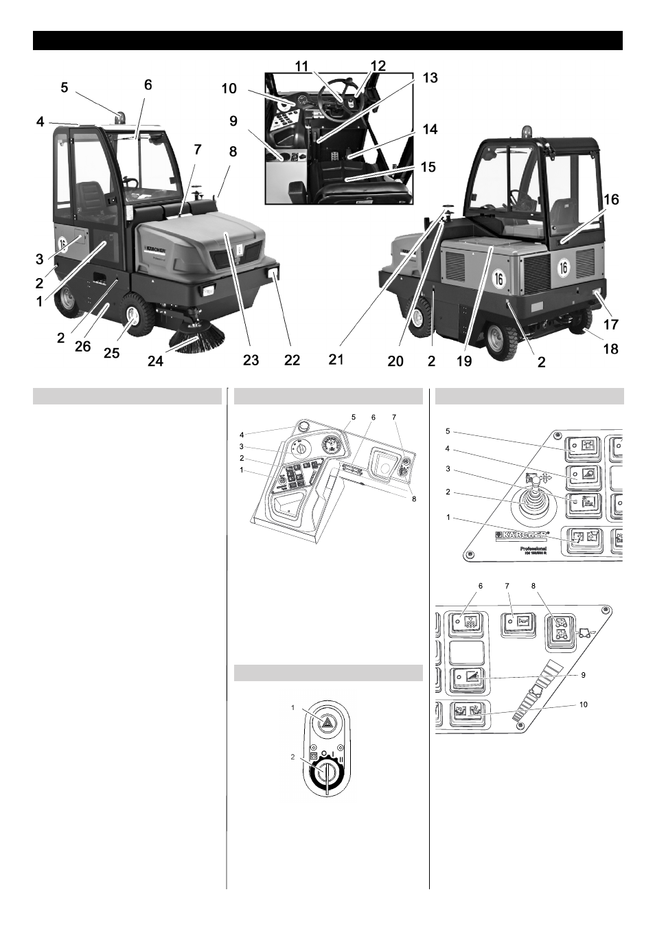
1 Cabin door (option)
2 Lashing point (4x)
3 Tank door
4 Driver cabin (optional)
5 Beacon lamp
6 Windshield wiper (option)
7 Lock of appliance hood
8 Blinker (option)
9 Heating/air conditioning (option)
10 Operating field
11 Steering wheel
12 Ignition lock
13 Parking brake
14 Pedals
15 Seat (with seat contact switch)
16 Ventilation grille (option)
17 Lighting system (optional)
18 Rear wheel
19 Engine cover
20 Brush roller adjustment
21 Centrifugal separator
22 Lighting system (optional)
23 Waste container
24 Side brushes
25 Front wheel
26 Roller brush
1 Adjustment lever, third side brush (op-
tion)
2 Function keys
3 Programme switch
4 Ventilation opening (option)
5 Multifunction display
6 Fuse box - work station
7 Warning system (option)
8 Ignition lock
1 Warning system (option)
2 Ignition key
–
Filament symbol : Pre-heat
–
Position 0: Switch off engine
–
Position 1: Ignition on
–
Position 2: Start the engine
1 Raise/lower waste container
2 Adjustment lever, third side brush (op-
tion)
3 Third side brush on/off
4 Work lights on/off
5 Beacon lamp on/off
6 Filter dedusting
7 Horn
8 Blinker switch
9 Irrigation of side brush (optional)
10 Open/close container lid
Operating and Functional Elements
Illustration of sweeper
Operating field
Ignition switch
Function keys
19
EN