Haltech Platinum PRO PLUG-IN Mitsubishi Evolution 9 2005 - 2007 (HT055064) User Manual
Page 11
4.
Remove the 3 x 10mm mounting bolts from the factory ECU Bracket.
Un-clip the ECU connector cover at the connector end of the ECU.
Disconnect the 3 connectors of the ECU from the wiring harness.
Remove the ECU and Mounting bracket from its location.
Figure 4 – OEM ECU in Original Mounting Position
5.
Remove the OEM ECU mounting bracket from the ECU by sliding a flat screwdriver
in-between the ECU and the bracket lugs to release.
Attach the supplied mounting captive nuts to the Haltech ECU 55mm away from
the rear of the unit (Map sensor nipple end) along the outer grooves in the extrusion.
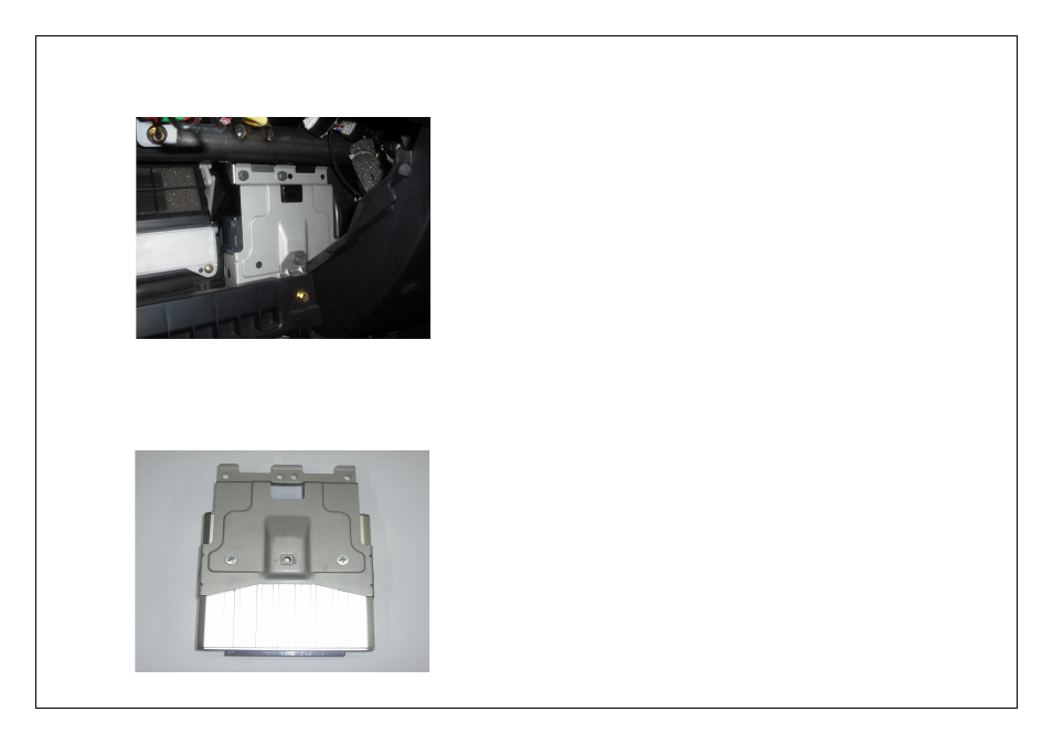
Attach the OEM bracket to the Haltech ECU using the 2 screws supplied.
Figure 5 – Haltech ECU with original mounting bracket fitted
Digital Pulsed Outputs ( DPO )
Digital Pulsed Outputs are capable of producing pulsed waveforms with varying duty
and frequency. DPO's can be used to control various devices such as thermo-fans,
shift lights, bypass air control valves, boost control solenoids etc.
When a Digital Pulsed output is activated by the ECU the output will switch to ground.
Solenoid valves and shift lights etc can be run directly from the output, however
high current devices such as thermo-fans and additional fuel pumps must be activated
through a relay. This way the DPO is only switching a relay and not a high current
draw device.
Two additional outputs can be connected using the Optional Rear Auxiliary
Harness ( HT040003 )
Digital Pulsed Outputs are limited to 800mA Max current draw.
Digital Switched Outputs ( DSO )
Digital Switched Outputs are capable of switching to ground
DSO's can be used to control relays in an on / off state only.
Two additional outputs can be connected using the Optional Rear Auxiliary
Harness ( HT040003 )
Digital Switched Outputs are limited to 800mA Max current draw.
Analogue Voltage Inputs ( AVI )
Analogue Voltage Inputs accept variable voltage inputs from 0V to 5V. These inputs
can also accept switch inputs that change between two different voltage levels.
The On Voltage and Off Voltage define what the thresholds are between the On and Off
states. The Voltage can be viewed as a channel in the software to determine the
thresholds for a switched input.
Two additional sensors or switched inputs can be connected using the
Optional Rear Auxiliary Harness ( HT040003 )
Analogue Temperature Inputs ( ATI )
Analogue Temperature Inputs accept variable resistance sensors.
These inputs have a pull – up resistor connected to them to allow them to be used with
most automotive temperature senders ( Variable resistance thermistor types ).
Two additional sensors can be connected using the Optional Rear Auxiliary
Harness ( HT040003 )
Wire connections
When using crimp connectors ensure that the correct crimping tool is used – if in
doubt do a pull test on a crimp connector, the wire should break before the wire
pulls out of the crimp. Terminal soldering can weaken a connection and should only
be used as a last resort. If solder joints are used, ensure joints are well isolated
from movement as solder joints are prone to fracture.
When splicing 2 wires it is preferable to use a crimp splice – again if using a solder
joint, ensure joint is limited in its range of possible movement as solder joints are
prone to fracture. Always use heat-shrink sleeving to insulate wires.