Spektrum SPMAR12100 User Manual
Page 11
Spektrum AR12100
19
Spektrum AR12100
20
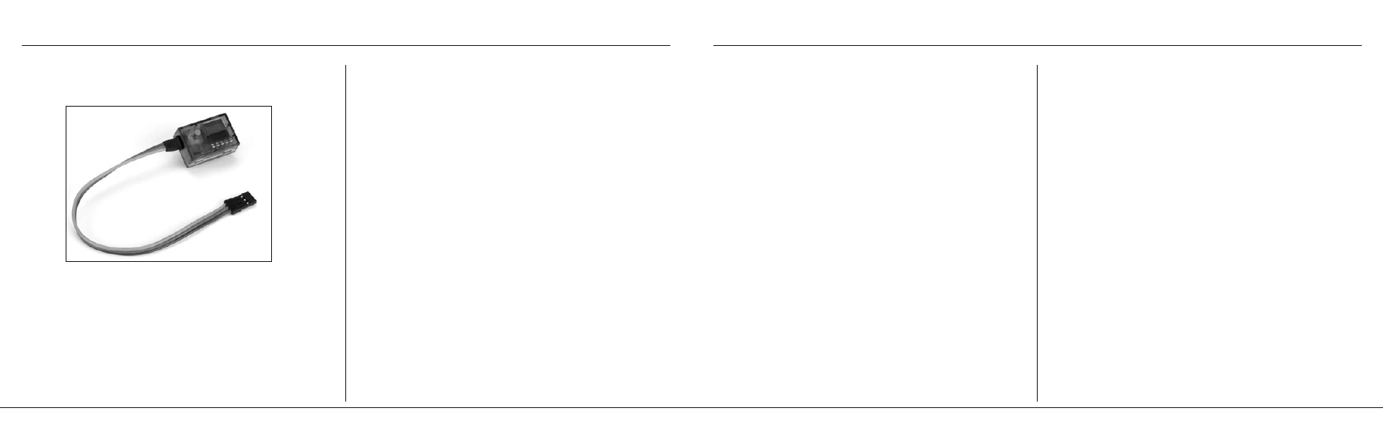
Spektrum’s Flight Log (SPM9540) is compatible with the AR12100 PowerSafe.
The Flight Log displays overall RF link performance as well as the individual
internal and external receiver link data. Additionally it displays receiver voltage.
Using the Flight Log
After a flight and before turning off the receiver or transmitter, plug the Flight
Log into the Data port on the PowerSafe. The screen will automatically
display voltage e.g. 6v2= 6.2 volts.
Note: When the voltage reaches 4.8 volts or less, the screen will flash indicating
low voltage.
Press the button to display the following information:
A - Antenna fades on antenna A
B - Antenna fades on antenna B
L - Antenna fades on the left antenna
R - Antenna fades on the right antenna
F - Frame loss
H - Holds
Antenna fades—represents the loss of a bit of information on that specific
antenna. Typically it’s normal to have as many as 50 to 100 antenna fades
during a flight. If any single antenna experiences over 500 fades in a single
flight, the antenna should be repositioned in the aircraft to optimize the RF link.
Frame loss—represents simultaneous antenna fades on all attached receivers.
If the RF link is performing optimally, frame losses per flight should be less
than 20. The antenna fades that caused the frame loss are recorded and will be
added to the total antenna fades.
A Hold occurs when 45 consecutive frame losses occur. This takes about one
second. If a hold occurs during a flight, it’s important to reevaluate the system,
moving the antennas to different locations and/or checking to be sure the trans-
mitter and receivers are all working correctly. The frame losses that led to the
hold are not added to the total frame losses.
Note: A servo extension can be used to allow the Flight Log to more conveniently be
plugged in without having to remove the aircraft’s hatch or canopy. On some models, the
Flight Log can be plugged in, attached and left on the model using double-sided tape.
This is common with helicopters, mounting the Flight Log conveniently to the side frame.
Flight Log
The remote receivers now included with the AR12100 feature
QuickConnect with Brownout Detection. Should a power interruption occur
(brownout), the system will reconnect immediately when power is restored
and the LEDs on each connected receiver will flash indicating a brownout
(power interruption) has occurred. Brownouts can be caused by an
inadequate power supply (weak battery or regulator), a loose connector, a
bad switch, an inadequate BEC when using an electronic speed controller,
etc. Brownouts occur when the receiver voltage drops below 3.2 volts thus
interrupting control as the servos and receiver require a minimum of 3.2
volts to operate.
How Brownout Detection Works
When the receiver voltage drops below 3.2 volts the system drops out
(ceases to operate). When power is restored, the receivers will immediately
attempt to reconnect to the last two frequencies they were connected to.
If the two frequencies are present (the transmitter was left on) the system
reconnects, typically in about 4ms. The receivers will then blink indicating
a brownout has occurred. If at any time the receiver is turned off then
back on and the transmitter is not turned off, the receivers will blink as a
power interruption was induced by turning off the power to the receiver.
In fact this simple test (turning the receiver off then on) will allow you to
determine if your system’s brownout detection is functioning.
Note: If a brownout occurs in-flight it is vital that the cause of the brownout be
determined and corrected. QuickConnect and Brownout Detection are designed to
allow you to safely fly through most short duration power interruptions. However, the
root cause of these interruptions must be corrected before the next flight to prevent
catastrophic safety issues.
QuickConnect
™
with Brownout Detection