Allied Telesis Port Interface Card User Manual
Page 4
4
Port Interface Card
C613-04020-00 REV D
two base-unit PIC bays, installing an AT-AR040 NSM provides four
additional PIC bays.
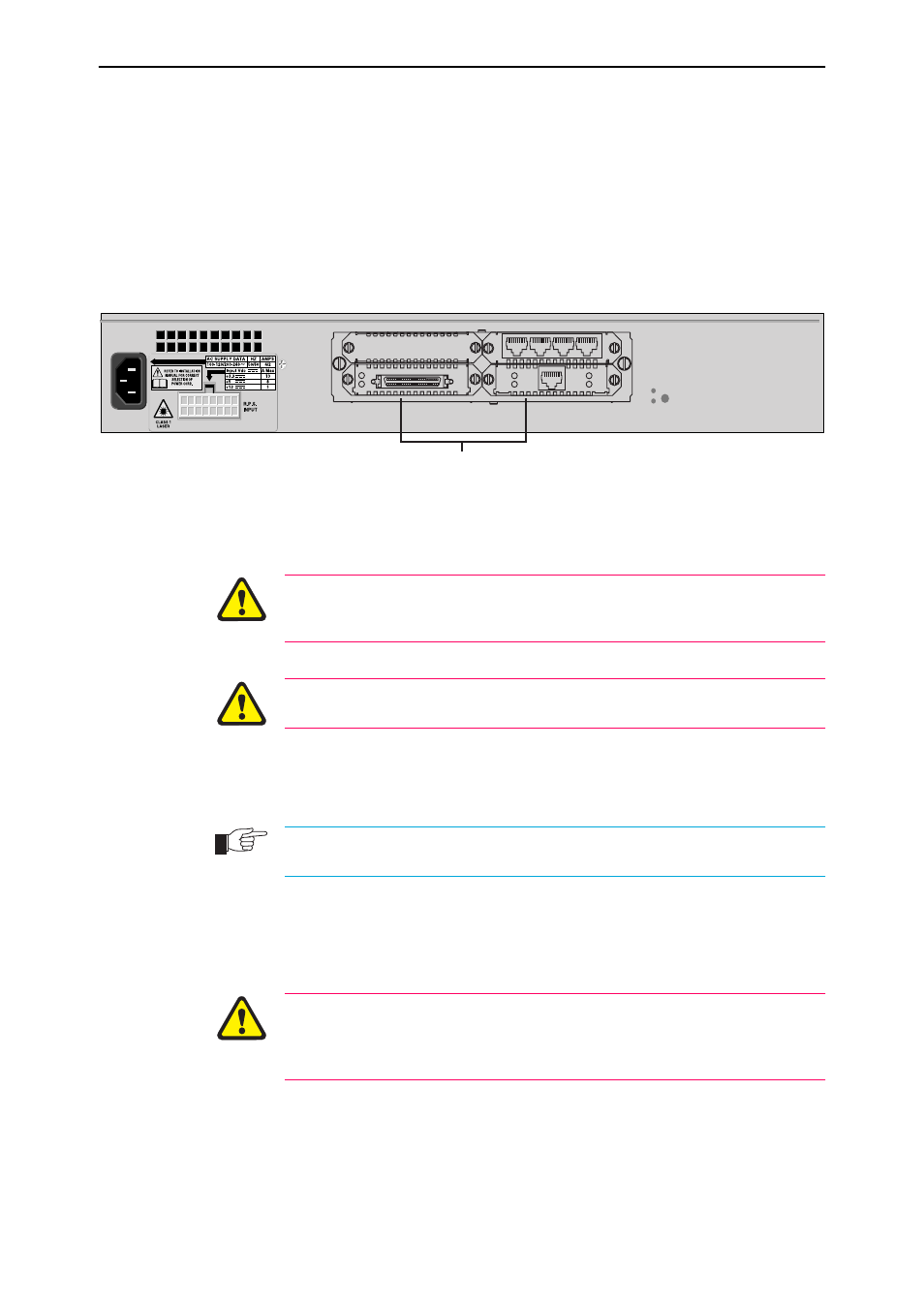
NSMs are installed in the rear panel of AR800 Series Switching Routers,
Rapier Switches, and AR740 Routers, see Figure 1. Contact your
Authorised Allied Telesyn distributor or reseller for more information on
how to purchase an NSM.
Note that the AT-AR022 ETH PIC is not recommended for use with the AT-
AR040 NSM.
Figure 1: An AT-AR40 NSM (with 3 PICs) installed in an AR824.
4.
If connected, disconnect the switch or router from its redundant power supply.
5.
Disconnect the switch or router from its AC or DC power supply.
Be sure to disconnect the main power supply and the redundant power supply
before installing a PIC. Installing a PIC with the switch or router powered ON
can damage the PIC.
For instructions on how to disconnect your switch or router, see the
documentation that is bundled with each switch or router.
6.
Remove the PIC-bay face-plate, NSM PIC-bay face-plate, or existing PIC.
Loosen the thumb screws to remove the face-plate or PIC.
Keep the face-plate for future use. If you remove the PIC, replace the face-plate to prevent
dust and debris from entering the switch or router and to maintain proper airflow.
7.
Unpack the PIC.
In an antistatic environment, remove the PIC from its packing material. Be
sure to observe ESD precautions.
Do not attempt to install a PIC or any other expansion option without
observing correct antistatic procedures. Failure to do so may damage the switch
or router, PIC, or expansion option. If you are unsure what the ‘correct’
procedures are, contact your Authorised Allied Telesyn distributor or reseller.
NSM with 3 PICs
SYN
Tx
Rx
Active
D Data
B Data
PRI E1/T1
N
ASYN
3
0