Allied Telesis AT-8288XL/SC User Manual
Page 15
AT-8216FXL, AT-8224XL, and AT-8288XL Series Quick Install Guide
5
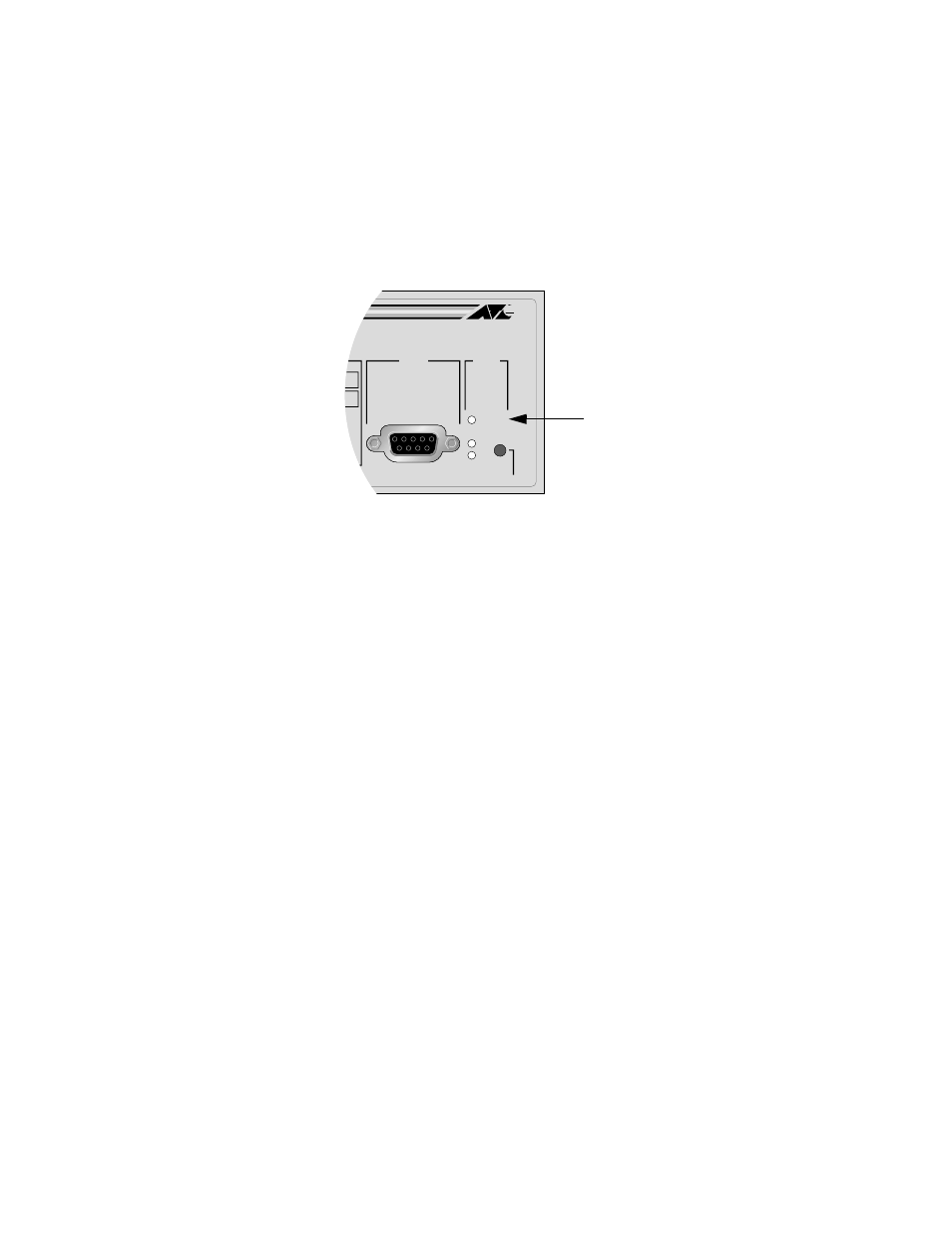
As power is applied to the switch, the Fault LED (shown in Figure 2)
flashes as the switch runs a series of internal self tests. After the switch
has finished running its self tests, the Fault LED will stop flashing and
will remain off. Refer to the section “Switch LEDs” on page 9 for
information on all of the System and Port LEDs.
Figure 2 Fault LED
5.
Connect the data cables, making sure each connection has a good valid link
and that the switch is receiving packets. For 10/100Base-TX ports, use a
straight-through cable to connect to workstations and servers, or use a
crossover cable to connect to hubs, routers, or other switches.
6.
Go to the procedure “Setting Up for Local Management” on page 8 to access
the Omega management interface on the switch.
STATUS
RESET
FAULT
RPS
PWR
RS-232
TERMINAL PORT
OL
Fault LED