Allied Telesis AT-PB10 Series User Manual
Page 2
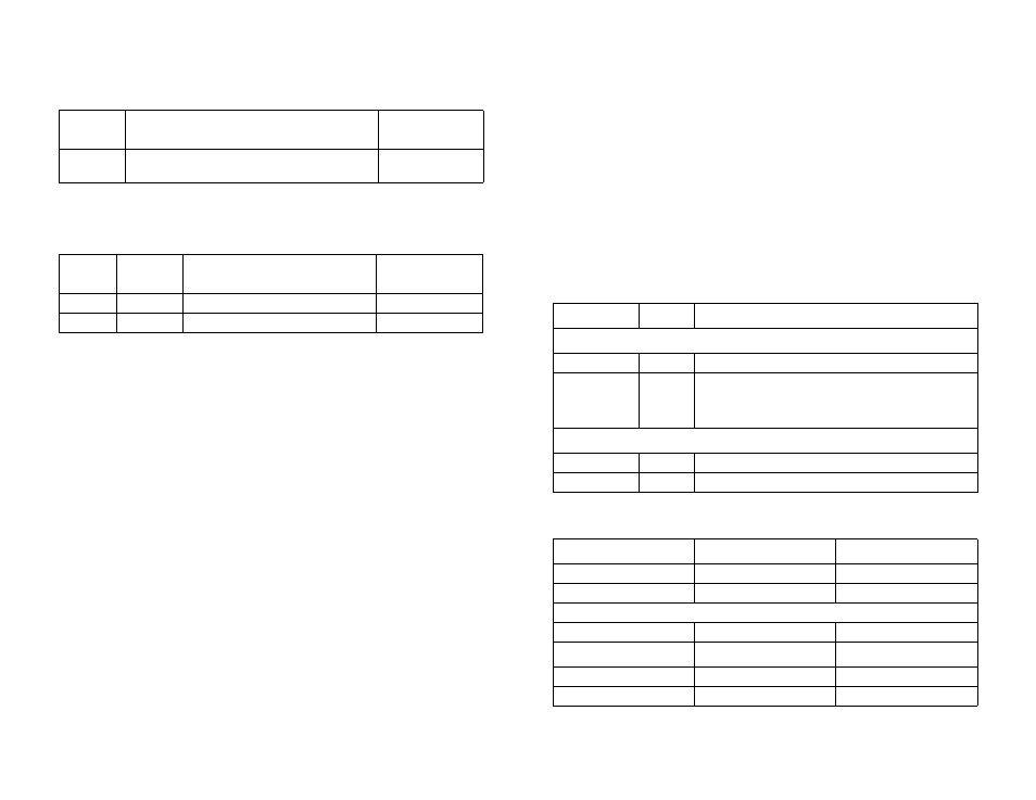
Cable Specifications
The following table lists the cable specifications for the 10Base-T twisted pair
port on all AT-PB10 series modules.
The second port on the AT-PB15 has a BNC connector with a maximum
operating distance of 185 meters (606 feet). The following table lists the cable
specifications for the 10Base-F fiber optic port on the AT-PB13 and AT-PB14
when operating in full-duplex mode.
Cable specifications for half-duplex operation can be found in the PowerBlade
Chassis Installation Guide.
Package Contents
Make sure the following items are included in your package. If any item is
missing or damaged, contact your Allied Telesyn sales representative for
assistance.
❑
One AT-PB10 Series Media Converter Module
❑
This quick install guide
❑
Warranty card
Installing the Media Converter
1. Remove a blank faceplate from an empty expansion slot on the front of the
chassis. The module can be installed in any expansion slot.
2. Remove the module from the shipping package and store the packaging
material in a safe place. Be sure to observe standard ESD precautions.
3. For an AT-PB15 module, check the setting of the J5 jumper. If the chassis
does not contain an AT-PBM02 management module, set the jumper to the
disabled position. Refer to the PowerBlade Chassis Installation Guide for
the jumper location.
4. Slide the module into the expansion slot, aligning it with the guiderails
until it firmly connects to the chassis’ backplane.
5. Secure the module to the chassis by tightening the thumbscrew.
6. Verify that the PR LED on the front of the unit is green.
7. Set the LT/ML switch to the ML (MissingLink) position (AT-PB13 or
AT-PB14 only).
8. Set the MDI/MDI-X switch for the 10Base-T port to the appropriate
setting.
9. Connect the data cables.
10. The AT-PB10 series module is now ready for use. Repeat this procedure to
install additional AT-PB10 series modules.
Refer to the PowerBlade Chassis Installation Guide for additional
information.
Status LEDs
Fiber Optic Interface (Multimode)
Connector
Type of Twisted Pair Cable
Maximum
Operating Distance
RJ-45
Unshielded/Shielded Twisted Pair Category 3 or
better
100 m (328 ft)
Model
Connector
Type of Fiber Optic Cable
Maximum
Operating Distance
AT-PB13
ST
50/125 µm or 62.5/125 µm multimode
2 km (1.2 mi)
AT-PB14
SC
50/125 µm or 62.5/125 µm multimode
2 km (1.2 mi)
LED
Color
Description
System LEDs
PR
Green
Power is applied to the media converter.
ML
Green
OFF
The MissingLink feature is activated.
The MissingLink feature is disabled and the unit is
performing a link test.
Port LEDs
LK
Green
A link is established on the port.
RX
Green
Data is being received or transmitted by the port.
Receiver
Typical
Range
Sensitivity
-30 dBm
N/A
Saturation
170 µW (-7.6 dBm)
150 µW (-8.2 dBm)
Transmitter
Wavelength
830 nm
±
20 nm
Output Power
Typical
Worst
62.5/125 mM
-12 dBm
-15.0
50/125 mM
-16.5 dBm
-19.5 dBm
2
3