Allied Telesis AT-PB100 Series User Manual
Page 2
The following table lists the cable specifications for the 100Base-FX fiber optic
port when operating in full-duplex mode.
Cable specifications for half-duplex operation can be found in the PowerBlade
Chassis Installation Guide.
Package Contents
Make sure the following items are included in your package. If any of these
items are missing or damaged, contact your Allied Telesyn sales
representative.
❑
One AT-PB100 Series Media Converter Module
❑
This quick install guide
❑
Warranty card
Installing the Media Converter
1. Remove a blank faceplate from an empty expansion slot on the front of the
chassis. The module can be installed in any slot.
2. Remove the module from the shipping package and store the packaging
material in a safe place. Be sure to observe standard ESD precautions.
3. Set the Auto-negotiation switch on the board to activate or deactivate
auto-negotiation of the duplex mode on the unit.
4. Slide the module into the expansion slot, aligning it with the guiderails
until it firmly connects to the chassis’ backplane.
5. Secure the module to the chassis by tightening the thumbscrew.
6. Verify that the PR LED on the front of the module is green.
7. Set the LT/ML switch to the LT (Link Test) position.
8. Set the MDI/MDI-X switch for the 100Base-TX port to the appropriate
setting.
9. Connect the data cables. The AT-PB100 series module is now ready for
use.
10. Repeat this procedure to install additional AT-PB100 series modules.
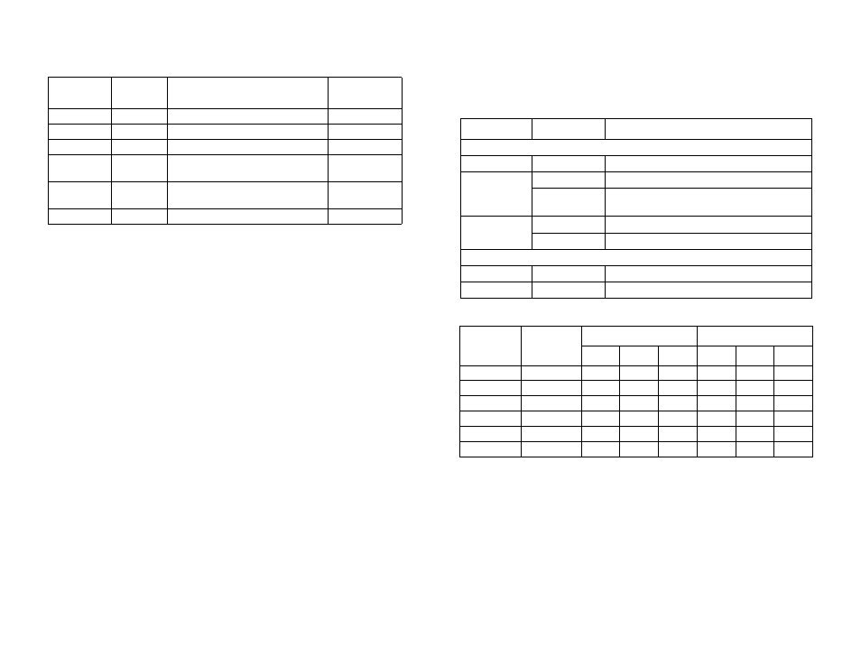
Status LEDs
Fiber Optic Port Specifications
Technical Specifications
Maximum Operating Temperature:
0° C to 40° C (32° F to 104° F)
Maximum Storage Temperature:
-20° C to 80° C (-4° F to 176° F)
Operating Altitude:
Up to 3,048 meters (10,000 feet)
Humidity:
5% to 80% (non-condensing)
EMC:
FCC Class A, EN55022 Class A,
EN55024
Safety:
EN60825, EN60950, UL1950 (UL/cUL)
Model
Type of
Connector
Type of Fiber Optic Cable
Maximum
Distance
AT-PB101
ST
50/125 µm or 62.5/125 µm multimode
2 km (1.2 mi)
AT-PB102
SC
50/125 µm or 62.5/125 µm multimode
2 km (1.2 mi)
AT-PB103/1
SC
9/125 µm single-mode
15 km (9.3 mi)
AT-PB103/2
SC
9/125 µm single-mode
40 km
(24.8 mi)
AT-PB103/3
SC
9/125 µm single-mode
75 km
(46.5 mi)
AT-PB103/4
SC
9/125 µm single-mode
100 km (62 mi)
LED
Color
Description
System LEDs
PR
Green
Power is applied to the media converter.
ML
Green
The MissingLink feature is activated.
OFF
The MissingLink feature is disabled and the unit is
performing a Link Test.
FD
Green
The ports are operating in full-duplex mode.
OFF
The ports are operating in half-duplex mode.
Port LEDs
LK
Green
A link is established on the port.
AT
Flashing Green
Data is being received or transmitted by the port.
Model
Wavelength
Transmitter Power
1
1.
Assumes 50/125 µm cable for the AT-PB103/1 and AT-PB103/2.
Receiver Sensitivity
Max.
Avg.
Min.
Min.
Avg.
Sat.
AT-PB101
1310 nm
-14.0
-20.3
-22.5
-31.8
-34.5
-14.0
AT-PB102
1310 nm
-14.0
-20.3
-22.5
-31.8
-34.5
-14.0
AT-PB103/1
1310 nm
-8.0
-11.5
-15.0
-31.0
-31.0
-8.0
AT-PB103/2
1310 nm
0.0
-3.0
-5.0
-35.0
-38.0
0.0
AT-PB103/3
1310 nm
0.0
-2.0
-4.0
-37.0
-37.0
-3.0
AT-PB103/4
1550 nm
0.0
-1.5
-3.0
-37.0
-37.0
-3.0
2
3