Allied Telesis AT-MC103ST/FSx User Manual
Page 34
Technical Specifications
22
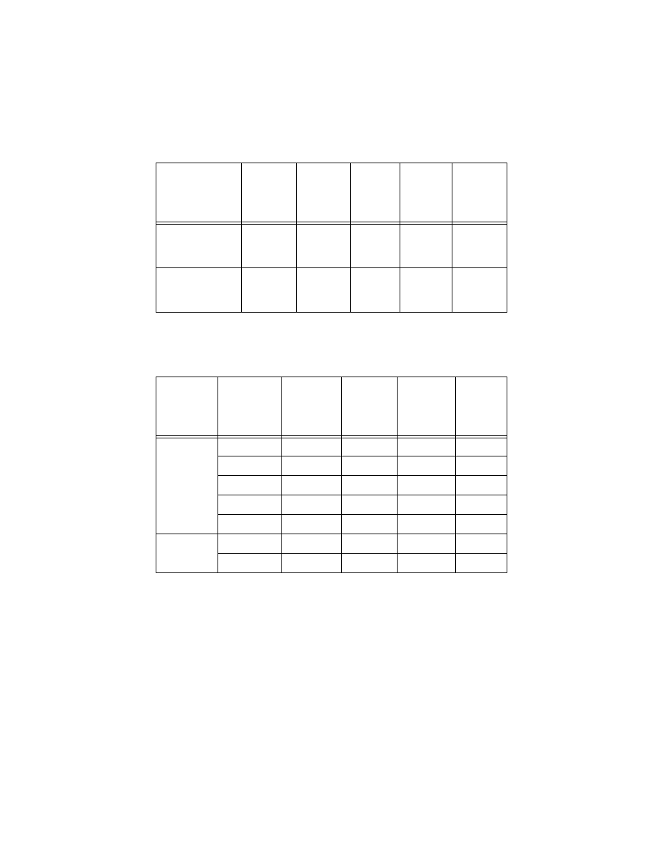
Table 9 Fiber Optic Loss Specifications (Benchmarks)
AT-MC103SC/FS3
and
AT-MC103ST/FS3
9/125 SMF
33.00 dB
35.00 dB
15 km
(9.4 mi)
75 km
(46.5 mi)
AT-MC103SC/FS4
and
AT-MC103ST/FS4
9/125 SMF
34.00 dB
35.50 dB
40 km
(24.8 mi)
100 km
(62 mi)
1. MMF = Multimode Fiber / SMF = Single-mode Fiber
2. The recommended minimum range is stated in all cases where the maximum transmitter output power exceeds
the receivers saturation level. This is to prevent blinding or burning out of the optical receiver on the far-end-node.
Fiber Type
1
1. MMF = Multimode Fiber / SMF = Single-mode Fiber
Fiber Optic
Diameter
(microns)
Optical
Wavelength
Typical
Loss
Factor
(dB/km)
Worst Case
Loss Factor
(dB/km)
Bandwidt
h (Mhz-
km)
MMF
50/125
850 nm
3.00
3.50
400
50/125
1310 nm
1.00
1.50
400
62.5/125
850 nm
3.00
3.75
200
62.5/125
1310 nm
1.00
1.50
500
100/140
850 nm
4.00
4.00
100
SMF
9/125
1310 nm
0.40
1.00
N/A
9/125
1550 nm
0.30
0.75
N/A
Table 8 Fiber Optic Datalink
(Continued)
Model
Fiber
Type
1
Minimum
Power /
Link
Budget
Average
Signal
Loss
Minimum
Distance
Spec.
2
Maximum
Distance
Spec.