Wiring and connecting a 12-50vdc powered unit – Allied Telesis AT-FS238b/2 User Manual
Page 38
Installing the Bridging Converter
28
Wiring and Connecting a 12-50VDC Powered Unit
To wire a 12-50VDC powered unit, perform the following step:
1.
Before wiring the bridging converter, review the following Warning
statements:
Warning
Only trained and qualified personnel are allowed to install or to replace
this equipment.
Warning
For 12-50VDC power connection, install this equipment only in a
Restricted Access Area.
2.
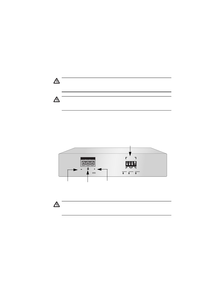
On the rear side of the chassis is a 3-prong receptacle connector labeled
12-50VDC. Starting from the left side of the terminal block, identify the
negative, ground, and positive terminals using either the diagram
adjacent to the terminal block or the illustration shown in
Figure 14.
Figure 14 Negative, Ground, and Positive Symbols
Warning
The power input must be provided from a SELV power source only, per
IEC 60950. Do not connect to a centralized DC battery bank.
12-50VDC
2
1
3
4
1
2
2 2
PORT
10
100
HALF
FULL
OFF
ON
DUPLEX
MODE
AUTO
NEG
SPEED
(Mbps)
DIP S
WITCHES
Negative
Positive
Ground