Allied Telesis AT-PB1000 Series User Manual
Page 2
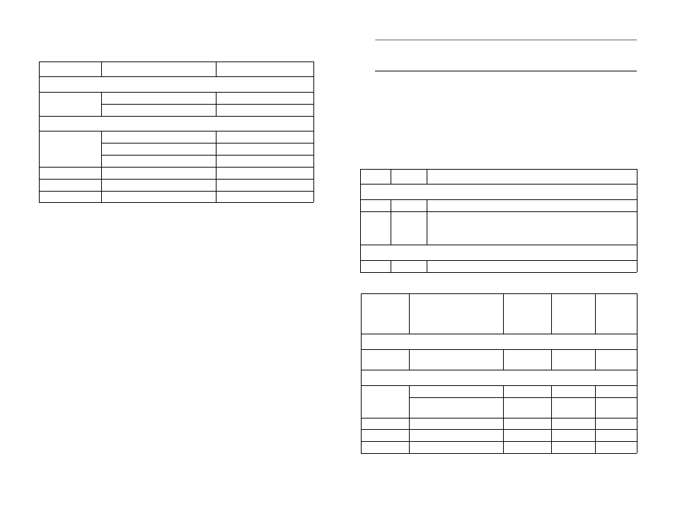
The following table lists the IEEE 802.3u cabling specifications for the AT-PB1000
Series modules when operating in full-duplex mode.
Cabling specifications for half-duplex operation can be found in the PowerBlade Chassis
Installation Guide.
Package Contents
Make sure the following items are included in your package. If any of these items are
missing or damaged, contact your Allied Telesyn sales representative.
❑
One AT-PB1000 Series Gigabit Media Converter
❑
This quick install guide
❑
Warranty card
Installing the Media Converter
1.
Remove a blank faceplate from an empty expansion slot on the front of the chassis.
The module can be installed in any slot.
2.
Remove the module from the shipping package and store the packaging in a safe
place. Be sure to observe standard ESD precautions.
3.
Slide the module into the expansion slot, aligning it with the guiderails, until it
firmly connects to the chassis’ backplane.
4.
Secure the module to the chassis by tightening the thumbscrew.
5.
Verify that the PR LED on the front of the module is green.
6.
Set the ML/LT switch to the LT (Link Test) position.
7.
Set the LT BB/LT SA button to either back to back or standalone, depending on your
topology. Refer to the PowerBlade Chassis Installation Guide for additional
information.
8.
Remove the dust covers from the fiber optic connectors and connect the data cables.
9.
Power ON the end nodes.
Note
End stations used with the media converter must operate with the same duplex
mode (either both full-duplex or both half-duplex mode).
10. Check that the LK LEDs on both ports on the media converter are green. If the
LEDs are OFF, refer to the PowerBlade Chassis Installation Guide for
troubleshooting instructions.
11. If the link test is successful, set the ML/LT switch to the ML (MissingLink) position.
The ML LED should be green. The media converter will not pass network traffic
when a link test is being performed.
12. Repeat this procedure to install additional AT-PB1000 Series modules.
Status LEDs
Fiber Optic Port Specifications
Port
Cable Type
Maximum Distance
1000Base-SX
All Models
62.5/125
µ
m multimode fiber
275 m (902 ft)
50/125
µ
m multimode fiber
550 m (1,804 ft)
1000Base-LX
AT-PB1001/1
62.5/12 5
µ
m multimode fiber
550 m (1,804 ft)
50/12 5
µ
m multimode fiber
550 m (1,804 ft)
10/125
µ
m single-mode fiber
10,000 m (32,800 ft)
AT-PB1001/2
10/125
µ
m single-mode fiber
20 km (12.4 mi)
AT-PB1001/3
10/125
µ
m single-mode fiber
50 km (31 mi)
AT-PB1001/4
10/125
µ
m single-mode fiber
70 km (43.4 mi)
LED
Color
Description
System LEDs
PR
Green
Power is applied to the media converter.
ML
Green
OFF
The MissingLink feature is activated.
The MissingLink feature is disabled and the media converter is operating in
the link test mode.
Port LEDs
LK
Green
A link has been established on the port.
Port
Cable
Transmitter
Output Power
(dBm avg.)
Wavelength
(nm)
Minimum
Receiver
Sensivity
(dBm avg.)
1000Base-SX
All Models
50/125 or 62.5/125 micron
multimode
-9.5 to -4.0
850
-17.0
1000Base-LX
AT-PB1001
10/125 micron single-mode
-9.5 to -3.0
1310
-20.0
50/125 or 62.5/125 micron
multimode
-11.5 to -3.0
1310
-20.0
AT-PB1001/2
10/125 micron single-mode
-3.0 to 0.0
1310
-24.0
AT-PB1001/3
10/125 micron single-mode
-5.0 to 0.0
1550
-24.0
AT-PB1001/4
10/125 micron single-mode
0.0 to 5.0
1550
-24.0
1
2