Table 2: rj45 pinout, Rj45—mdi pinout, Rj45—mdi-x pinout – Allied Telesis AT-MC12T User Manual
Page 2: Signal, Led explanation, Table 3: led guide, Led name, Meaning when led is lighted, Power requirements, 12 to 18 vdc, 700 ma
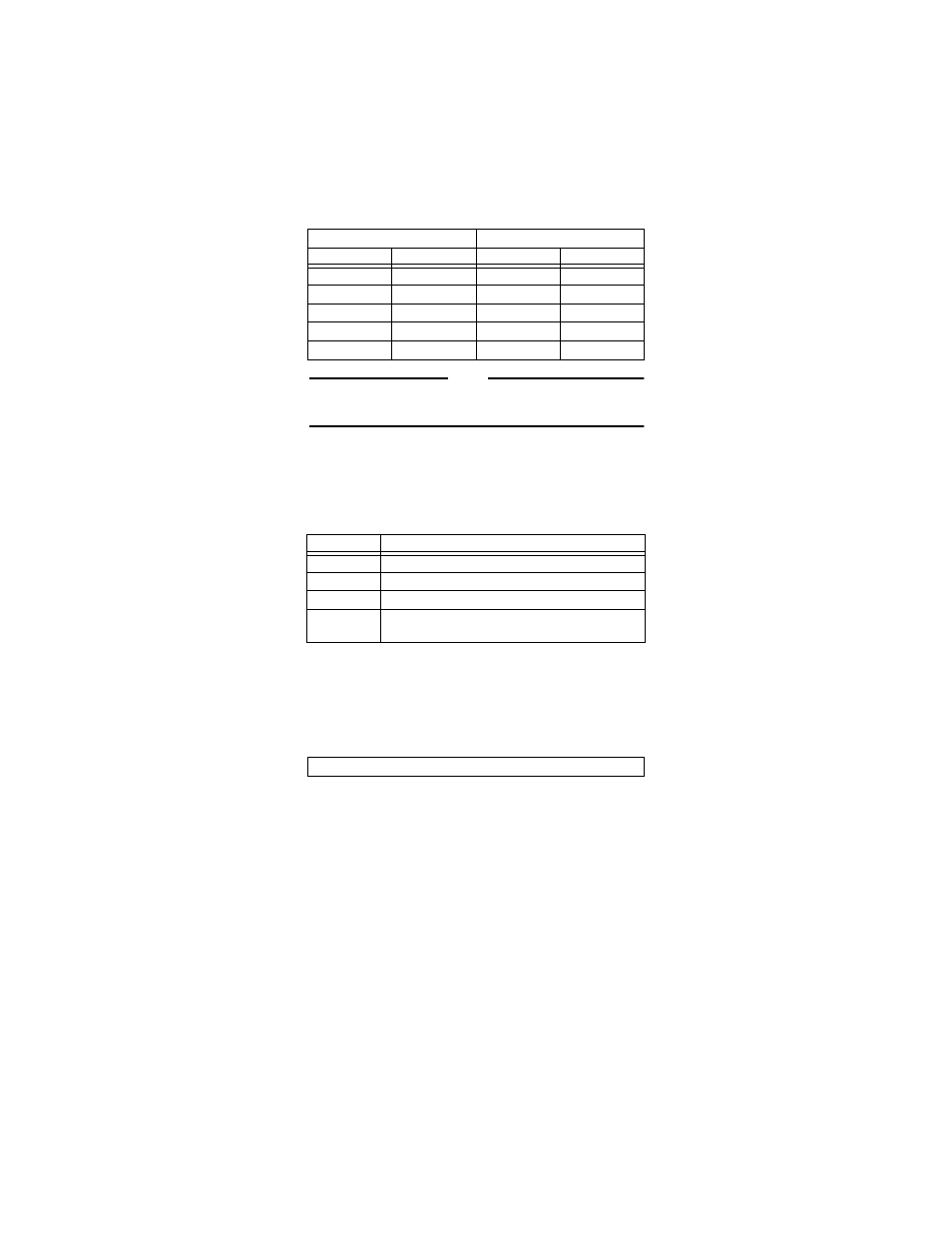
Table 2:
RJ45 Pinout
NOTE
The transceiver (MAU) attached at the AUI connector must have the
SQE (heartbeat) test disabled for proper operation.
LED Explanation
There are four LEDs next to the 10BASE-T port of the MC12T
Table 3:
LED Guide
Power Requirements
The AT-MC12T draws power from the wall-mount AC-DC power
adapter attached at its DC jack. ATI supplies the TUV/UL/CSA
licensed safety compliant AC power adapter for the 120 and 240 VAC
versions with an unregulated output of 12 VDC at 1A. The power
required for the AT-MC12T is:
Installing the AT-MC12T
1.
Choose the correct switch settings for the AT-MC12T and the
attached transceiver.
2.
Make sure that the SQE test is OFF.
3.
Plug the AT-MC12T onto the 15-pin male connector on the
transceiver or on the AUI cable.
4.
Slide the connector latch in place.
5.
Connect the power adapter to the AT-MC12T and then to an AC
outlet.
Warranty
The AT-MC12T Media Converter has a lifetime warranty. The power
supply has a one year warranty.
RJ45—MDI Pinout
RJ45—MDI-X Pinout
Pin
Signal
Pin
Signal
1
TD+
1
RD+
2
TD-
2
RD-
3
RD+
3
TD+
6
RD-
6
TD-
4, 5, 7, 8
N/A
4, 5, 7, 8
N/A
LED Name
Meaning When LED Is Lighted
PWR
Indicates power is applied
LNK
Indicates link is established
ACT
Indicates data is received on RJ45 or AUI port
COL
Indicates a collision is detected on RJ45 or AUI
port
12 to 18 VDC, 700 mA