Allied Telesis AT-PWR01 User Manual
Page 5
Quick Install Guide
5
C613-04049-01 REV B
5.
Remove an existing PSU or FOM
Disconnect the power cord before removing the PSU.
The PSU and switch may overheat or be damaged by dust and debris if bays are
left uncovered.
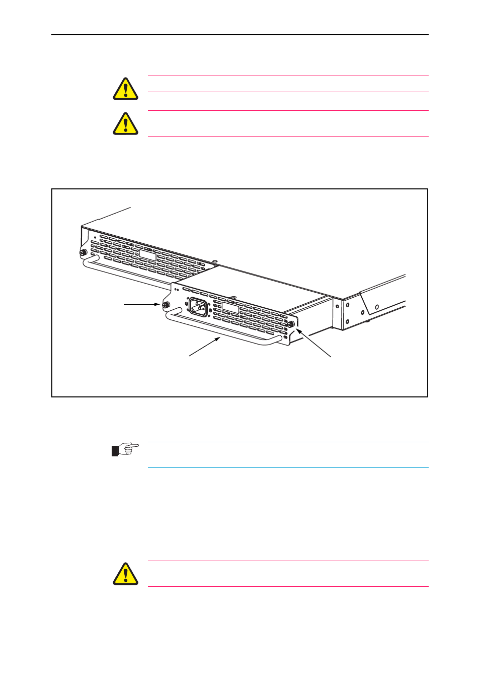
Loosen the two Phillips screws on the PSU or FOM until the screws
disengage from the switch chassis (see Figure 1).
Figure 1: Captive mounting screws on the AT-PWR01 and AT-FAN01
Slowly and carefully slide the PSU or FOM out of the switch’s power supply
bay.
If you remove a PSU, or FOM, from the switch replace the PSU, or FOM, to prevent
dust and debris from entering the switch chassis and to maintain proper airflow.
6.
Insert a PSU
Slowly and carefully slide the PSU into the switch’s power supply bay.
Firmly press the PSU home (until its front panel engages or nearly engages
the switch chassis).
7.
Secure the PSU
Keep the PSU in a straight alignment and insert it slowly. Forcing a misaligned
PSU is likely to damage the chassis and PSU.
Tighten the two Phillips screws on the PSU’s faceplate (see Figure 1 on
page -5).
Handle
Captive screw
Captive screw
PSU
Switch
8948PSU