Powering on a dc powered chassis, Technical specifications, Electrical safety and emission statement – Allied Telesis AT-PWR15 User Manual
Page 2: Physical and environmental, Electrical ratings
Powering On a DC Powered Chassis
This section describes how to power on a DC powered AT-CV5000 chassis.
Warning
As a safety precaution, a 15 Amp circuit breaker should be installed at
the supply end of the cable to be used with this LAN equipment.
ALWAYS connect the wiring to the LAN equipment first before
connecting the wiring to the breaker. To avoid the danger of physical
injury from electrical shock, do not work with HOT feeds. Always be
sure that the breaker is in the OFF position before connecting the wiring
to the breaker.
Note
A tray cable is required to connect the power source if the chassis is
powered by centralized DC power. The tray cable must be an UL listed
Type TC tray cable and rated at 600 V and 90 degree C, with three
conductors, minimum 14 AWG.
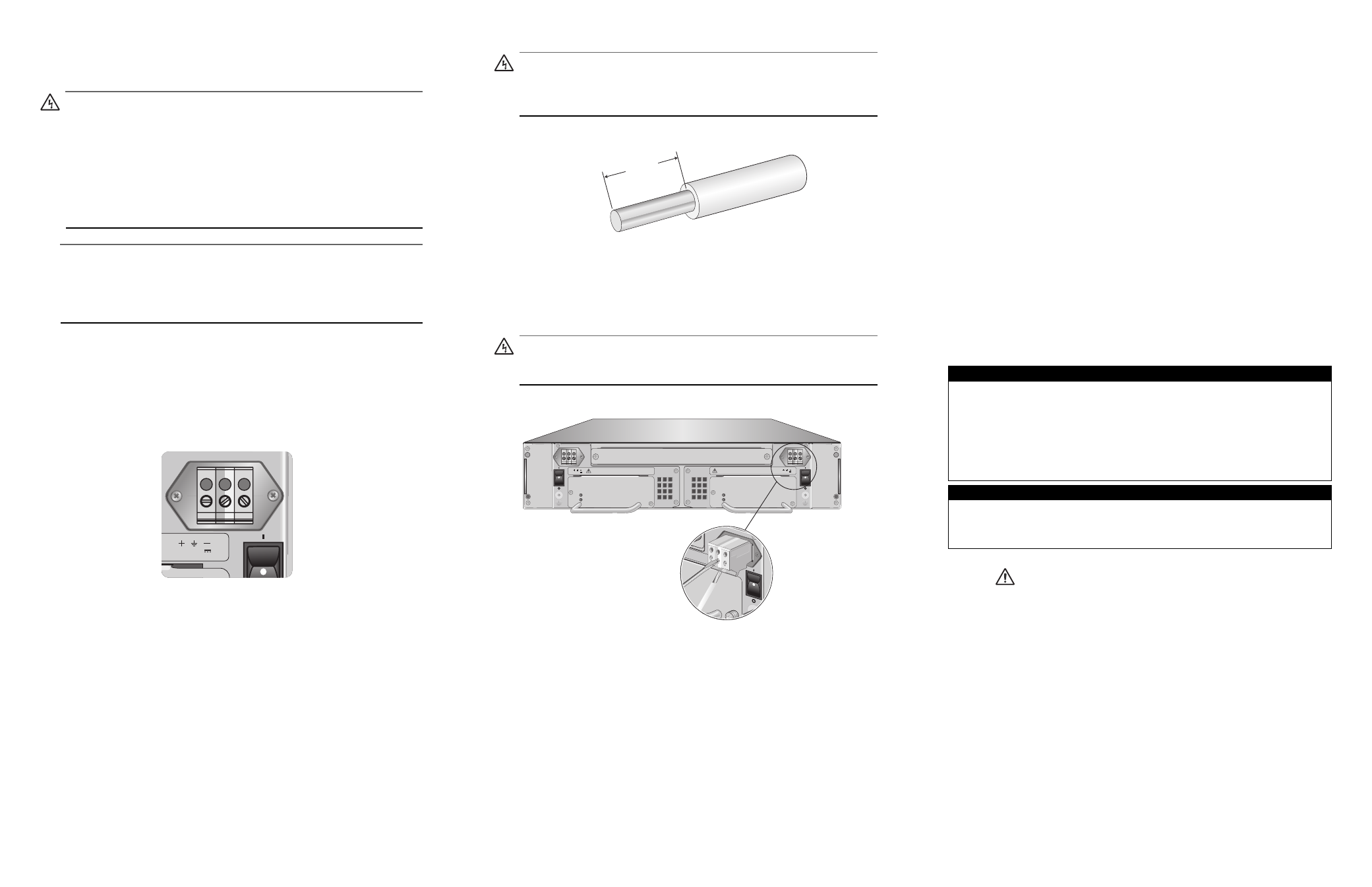
1. Make sure that the ON/OFF power switch is in the OFF position.
2. Locate the two DC terminal blocks, labeled A and B, on the rear panel of
the chassis.
3. Starting from the left side of a terminal block, identify the positive, power
supply ground and negative terminals using the symbols below the
terminal block in Figure 6.
Figure 6. DC Terminal Block
4. With a 14-gauge wire-stripping tool, strip the three wires in the tray cable
coming from the DC input power source to 8mm
± 1mm (0.31 in., ± 0.039
in.), as shown in Figure 7.
250
40-60VDC
Warning
Do not strip more than the recommended amount of wire. Stripping
more than the recommended amount can create a safety hazard by
leaving exposed wire on the terminal block after installation.
Figure 7. Stripped Wire
5. Connect the power supply ground wire into the middle of the three
terminals; this is the terminal marked with the ground symbol. Inserting the
wire into the terminal and tightening the connection with a flathead
screwdriver, as shown in Figure 8.
Warning
When installing this equipment, always ensure that the power supply
ground connection is installed first and disconnected last.
Figure 8. Inserting Wires into a DC Terminal Block
6. Connect the +48 VDC (RTN) feed wire to the terminal block marked
+ (plus).
7. Connect the -48 VDC feed wire to the terminal block marked - (minus).
8mm ±1mm
(0.31in. ±0.039 in.)
B
WR15
e pow
er inpu
t. To
isconn
ect all po
wer
FOR CENTRA
LIZED DC PO
WER
CONNECTION
, INST
ALL O
NLY IN
A RESTRICTE
D AREA.
POWER
FAULT
AT-PWR15
A
B
AT-CVFAN
A
AT-CVFAN
B
AT-PWR15
POWER
FAULT
40-60VDC
WARNING
This unit might have more than one power input. To
reduce the risk of electric shock, disconnect all power
inputs before servicing unit.
FOR CENTRALIZED DC POWER
CONNECTION, INSTALL ONLY IN
A RESTRICTED AREA.
40-60VDC
WARNING
This unit might have more than one power input. To
reduce the risk of electric shock, disconnect all power
inputs before servicing unit.
FOR CENTRALIZED DC POWER
CONNECTION, INSTALL ONLY IN
A RESTRICTED AREA.
256
Technical Specifications
Physical and Environmental
Dimensions (H x W x L)
3.67 cm x 10.1 cm x 17.1 cm
(1.45 in x 3.97 in x 6.73 in)
Weight
1.75 lbs
Operating Temperature
0° C to 40° C (32° F to 104° F)
Storage Temperature
-25° C to 70° C (-13° F to 158° F)
Operating Relative Humidity
5% to 90% RH (non-condensing)
Storage Relative Humidity
5% to 95% RH (non-condensing)
Operating Altitude Range
Up to 3,000 m (9,843 ft)
Electrical Ratings
DC Input Current:
40 to 60 VDC (6.0 A)
Nominal Input Frequency:
47-63 Hz
Electrical Safety and Emission Statement
Standards: This product meets the following standards when installed in compliant host equipment.
Emission
FCC Class A, EN55022 Class A, VCCI Class A, C-TICK, CE
WARNING:
In a domestic environment this product may cause radio interference in which case the
user may be required to take adequate measures.
Immunity
EN55024
Electrical Safety
UL60950-1 (
c
UL
us
), EN60950 (TUV), CAN/CSA C22.2 No. 60950-1-03
Copyright
© 2005 Allied Telesyn, Inc. All rights reserved.
No part of this publication may be reproduced without prior written permission from Allied Telesyn Inc.
U.S. Federal Communications Commission
RADIATED ENERGY
Note: This equipment has been tested and found to comply with the limits for a Class A digital device pursuant
to Part 15 of FCC Rules. These limits are designed to provide reasonable protection against harmful
interference when the equipment is operated in a commercial environment. This equipment generates, uses,
and can radiate radio frequency energy and, if not installed and used in accordance with this instruction
manual, may cause harmful interference to radio communications. Operation of this equipment in a residential
area is likely to cause harmful interference in which case the user will be required to correct the interference at
his own expense.
Note: Modifications or changes not expressly approved of by the manufacturer or the FCC, can void your right
to operate this equipment.
Industry Canada
This Class A digital apparatus meets all requirements of the Canadian Interference-Causing Equipment
Regulations.
Cet appareil numérique de la classe A respecte toutes les exigences du Règlement sur le matériel brouilleur
du Canada.
4
5
6