Electrical safety and emission statement, Installing an at-cv5pnl2 blank slot cover, Installing an at-cv5pnl3 blank slot cover – Allied Telesis AT-CV5PNLx Series Blank Slot Covers User Manual
Page 2: 240v ac
6. Use a Phillips screwdriver to tighten the captive screw, as shown in
Figure 5. Tightening the Captive Screw on an AT-CV5PNL1
7. Repeat this procedure to install additional AT-CV5PNL1 blank slot covers.
Installing an AT-CV5PNL2 Blank Slot Cover
The AT-CV5PNL2 blank slot cover is designed to cover any unoccupied
power supply module slots in the AT-CV5000 chassis model only.
To install an AT-CV5PNL2 blank slot cover, perform the following procedure:
1. Remove the AT-CV5PNL2 blank slot cover from its shipping package and
store the package in a safe place.
You must use the original package if you need to return the unit to Allied
Telesis.
2. Select the power supply slot in the AT-CV5000 chassis where you want to
install the blank slot cover.
3. Align the back edge of the blank slot cover with the alignment guides
located inside the slot.
4. Slide the blank slot cover into the slot, as shown in Figure 6, until the slot
cover is flush with the front of the chassis.
Figure 6. Inserting an AT-CV5PNL2 Blank Slot Cover
272
AT-CM202
LK
AT
T
X
ML/SM
L FD/OA
M
RDY
LK
AT
AT-CM202
LK
AT
T
X
ML/SML
FD/OAM
RDY
LK
AT
AT-CM202
LK
AT
T
X
ML/SML
FD/OAM
RDY
LK
AT
AT-CM202
LK AT
T
X
ML/SML
FD/OAM
RDY
LK AT
AT-CM202
LK AT
T
X
ML/SML
FD/OAM
RDY
LK
AT
100-240
VAC
~
WARNING
This un
it might h
ave mo
re than o
ne pow
er input.
To
reduce the
risk of e
lectric
shock, d
isconne
ct all p
ower
inputs b
efore s
ervicin
g unit.
226
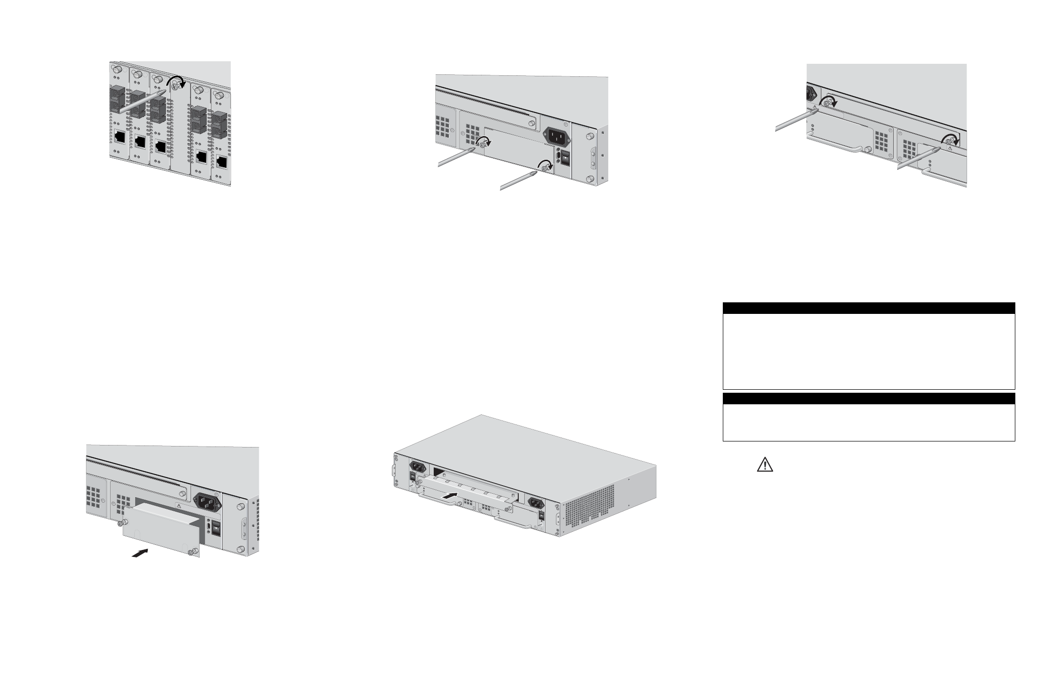
5. Use a Phillips screwdriver to tighten the captive screws, as shown in
Figure 7. Tightening the Captive Screws on an AT-CV5PNL2
6. Repeat this procedure to install additional AT-CV5PNL2 blank slot cover.
Installing an AT-CV5PNL3 Blank Slot Cover
The AT-CV5PNL3 blank slot cover is designed to cover the unoccupied
expansion slot located in the rear of the AT-CV5000 chassis.
To install an AT-CV5PNL3 blank slot cover, perform the following procedure:
1. Remove the AT-CV5PNL3 blank slot cover from its shipping package and
store the package in a safe place.
You must use the original package if you need to return the unit to Allied
Telesis.
2. Align the back edge of the blank slot cover with the alignment guides
located inside the slot.
3. Slide the blank slot cover into the slot, as shown in Figure 8, until the slot
cover is flush with the front of the chassis.
Figure 8. Inserting an AT-CV5PNL3 Blank Slot Cover
273
AT-CV5PW
R14
POWE
R
FAULT
AT-CV5PWRAC
A
B
AT-CV5FAN
B
POWE
R
FAULT
AT-CVFAN
A
227
100-240V
AC
~
WAR
NING
This u
nit mig
ht have
more t
han on
e pow
er inpu
t. To
reduce
the ris
k of ele
ctric s
hock, d
isconn
ect all p
ower
inputs
before
servic
ing un
it.
100-2
40VAC
~
WARN
ING
This u
nit m
ight h
ave m
ore th
an one
power in
put. To
reduce
the ris
k of ele
ctric
shock
, disco
nnect a
ll pow
er
inputs
before
servic
ing unit.
4. Use a Phillips screwdriver to tighten the captive screws, as shown in
Figure 9. Tightening the Captive Screws on an AT-CV5PNL3
You have completed the AT-CV5PNL3 blank slot cover installation procedure.
Electrical Safety and Emission Statement
Standards: This product meets the following standards when installed in compliant host equipment.
Emission
FCC Class A, EN55022 Class A, VCCI Class A, C-TICK, CE
WARNING:
In a domestic environment this product may cause radio interference in which
case the user may be required to take adequate measures.
Immunity
EN55024
Electrical Safety
UL60950 (UL/
c
UL), EN60950 (TUV), CSA22.2 No. 950
Copyright
2006 Allied Telesis, Inc. All rights reserved.
No part of this publication may be reproduced without prior written permission from Allied Telesis, Inc.
U.S. Federal Communications Commission
RADIATED ENERGY
Note: This equipment has been tested and found to comply with the limits for a Class A digital device pursuant
to Part 15 of FCC Rules. These limits are designed to provide reasonable protection against harmful
interference when the equipment is operated in a commercial environment. This equipment generates, uses,
and can radiate radio frequency energy and, if not installed and used in accordance with this instruction
manual, may cause harmful interference to radio communications. Operation of this equipment in a residential
area is likely to cause harmful interference in which case the user will be required to correct the interference at
his own expense.
Note: Modifications or changes not expressly approved of by the manufacturer or the FCC, can void your right
to operate this equipment.
Industry Canada
This Class A digital apparatus meets all requirements of the Canadian Interference-Causing Equipment
Regulations.
Cet appareil numérique de la classe A respecte toutes les exigences du Règlement sur le matériel brouilleur
du Canada.
274
POWER
FAULT
AT-PWR1
4
A
WAR
NING
This u
nit mig
ht ha
ve more
than
o
reduce
the
risk
of ele
ctric
shoc
k
inputs b
efore se
rvicing
unit.
40VA
C
~
WA
RNING
This u
nit m
ight h
ave m
ore th
an one
power
inp
ut. To
reduc
e th
e risk o
f electric
shock,
disco
nnect al
l power
inputs
before
servic
ing uni
t.
POWER
FAULT
AT-PWR1
4
4
5
6