Related documents, Verifying package contents, Fiber optic port specifications – Allied Telesis AT-G8BD-13/-14 Bidirectional GBIC User Manual
Page 2
Note
The GBIC transceivers can be hot-swapped. You do
not need to power off the networking device when you
install or replace a GBIC transceiver.
Related Documents
For details on the features and functions of your Allied
Telesyn product along with installation instructions, refer to
our web site, www.alliedtelesyn.com.
Verifying Package Contents
Verify that the correct components are included in your
package:
•
AT-G8BD-13 or AT-G8BD-14 transceiver
•
This installation guide
•
Warranty card
If any item is missing or damaged, contact your Allied
Telesyn sales representative for assistance.
Installing an AT-G8BD Bidirectional GBIC
Transceiver
To install a G8BD GBIC transceiver, perform the following
procedure:
Caution
The transceiver can be damaged by static electricity.
Be sure to observer all standard electrostatic discharge
(ESD) precautions, such as wearing an antistatic wrist
strap, to avoid damaging the device.
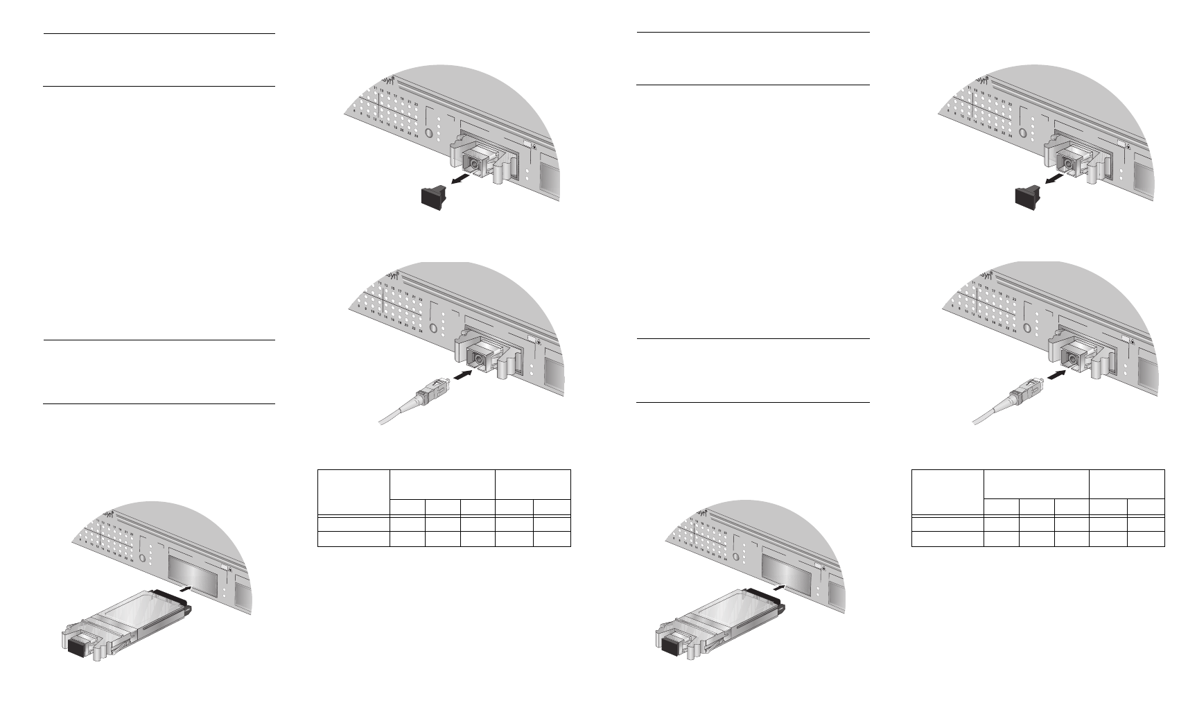
1.
Remove the transceiver from its shipping package and
store the package in a safe place. You must use the
original package if you need to return the unit to Allied
Telesyn.
2.
Slide the module into the GBIC slot in the Allied
Telesyn networking device.
Link
Mode
Link
Mode
100
FULL
ACT
MODE
COL
LINK
MODE
POR
T A
10Base-T/100Base-TX Fast E
thernet S
witch
CLAS
S 1
LASE
R PR
ODUC
T
DO N
OT ST
ARE
INTO
BEA
M
445
3.
Remove the dust cover from the single SC connector
on the GBIC.
4.
Connect the fiber optic cable to the single SC
connector on the transceiver.
Fiber Optic Port Specifications
Model
Optical Output Power
(dBm)
Optical Input
Power (dBm)
Min.
Avg.
Max
Min.
Max.
AT-G8BD-13
-3
0
+2
-24
+2
AT-G8BD-14
-3
0
+2
-24
+2
Link
Mode
Link
Mode
100
FULL
ACT
MODE
COL
LINK
MODE
POR
T A
10Base-T/100Base-TX Fast Ethernet Switch
CLAS
S 1
LASE
R PR
ODUC
T
DO N
OT ST
ARE
INTO
BEA
M
446
Link
Mode
Link
Mode
100
FULL
ACT
MODE
COL
LINK
MODE
POR
T A
10Base-T/100Base-TX Fast Ethernet Switch
CLAS
S 1
LASE
R PR
ODUC
T
DO N
OT ST
ARE
INTO
BEA
M
447
Note
The GBIC transceivers can be hot-swapped. You do
not need to power off the networking device when you
install or replace a GBIC transceiver.
Related Documents
For details on the features and functions of your Allied
Telesyn product along with installation instructions, refer to
our web site, www.alliedtelesyn.com.
Verifying Package Contents
Verify that the correct components are included in your
package:
•
AT-G8BD-13 or AT-G8BD-14 transceiver
•
This installation guide
•
Warranty card
If any item is missing or damaged, contact your Allied
Telesyn sales representative for assistance.
Installing an AT-G8BD Bidirectional GBIC
Transceiver
To install a G8BD GBIC transceiver, perform the following
procedure:
Caution
The transceiver can be damaged by static electricity.
Be sure to observer all standard electrostatic discharge
(ESD) precautions, such as wearing an antistatic wrist
strap, to avoid damaging the device.
1.
Remove the transceiver from its shipping package and
store the package in a safe place. You must use the
original package if you need to return the unit to Allied
Telesyn.
2.
Slide the module into the GBIC slot in the Allied
Telesyn networking device.
Link
Mode
Link
Mode
100
FULL
ACT
MODE
COL
LINK
MODE
POR
T A
10Base-T/100Base
-TX Fa
st Ethernet Sw
itch
CLAS
S 1
LASE
R PR
ODUC
T
DO N
OT ST
ARE
INTO
BEA
M
445
3.
Remove the dust cover from the single SC connector
on the GBIC.
4.
Connect the fiber optic cable to the single SC
connector on the transceiver.
Fiber Optic Port Specifications
Model
Optical Output Power
(dBm)
Optical Input
Power (dBm)
Min.
Avg.
Max
Min.
Max.
AT-G8BD-13
-3
0
+2
-24
+2
AT-G8BD-14
-3
0
+2
-24
+2
Link
Mode
Link
Mode
100
FULL
ACT
MODE
COL
LINK
MODE
POR
T A
10Base-T/100Base-TX Fast Ethernet Switch
CLAS
S 1
LASE
R PR
ODUC
T
DO N
OT ST
ARE
INTO
BEA
M
446
Link
Mode
Link
Mode
100
FULL
ACT
MODE
COL
LINK
MODE
POR
T A
10Base-T/100Base-TX Fast Ethernet Switch
CLAS
S 1
LASE
R PR
ODUC
T
DO N
OT ST
ARE
INTO
BEA
M
447