Allied Telesis Network Service Module AR040-48 User Manual
Page 5
Quick Install Guide
5
C613-04019-01 REV J
4.
Remove the switch or router NSM-bay face-plate or existing NSM
If the switch or router does not have an NSM installed, remove the blank
NSM-bay face-plate by loosening the two M4 Phillips screws. See Figure 3
on page 5.
If an NSM is already installed, disconnect its network cables and TNV lines
before removing it from the switch or router.
Remove the NSM by unscrewing both thumbscrews at the same time. As
the thumbscrews are turned, they will push the NSM out of the bay.
If the NSM has extractor levers, moving them to the open position will
assist the removal process (Figure 2 on page 5).
Figure 2: NSM extractor levers.
When removing an NSM, take care to turn each thumbscrew by an equal
amount to ensure the NSM does not become misaligned. Forcing a jammed
thumbscrew may damage the NSM.
If a thumbscrew becomes tight, it must not be forced. Instead, screw it in or
out slightly to loosen it and then try again, taking care to unscrew both
thumbscrews at the same rate.
Keep the face-plate for future use. If you remove an NSM, replace the face-plate to
prevent dust and debris from entering the switch or router and to maintain proper
airflow.
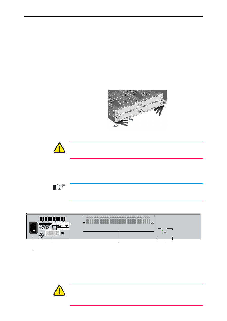
Figure 3: The NSM bay on a Rapier Switch.
5.
Prepare the NSM
In an antistatic environment, remove the NSM from its packing material.
Be sure to observe ESD precautions.
Do not attempt to install an NSM without observing correct antistatic
procedures. Failure to do so may damage the switch, router, or NSM. If you are
unsure what the correct procedures are, contact your authorised Allied Telesis
distributor or reseller.
Open
Close
NSM 0
Hot Swap
In Use
Swap
NSM bay
Base unit LEDs
RPS inlet
AC power inlet (AC models only)