Hot swapping an, Testing and troubleshooting the installation, Warranty registration – Allied Telesis AT-PWR9 User Manual
Page 2: Specifications, Electrical, safety, and emissions statements
4
5
6
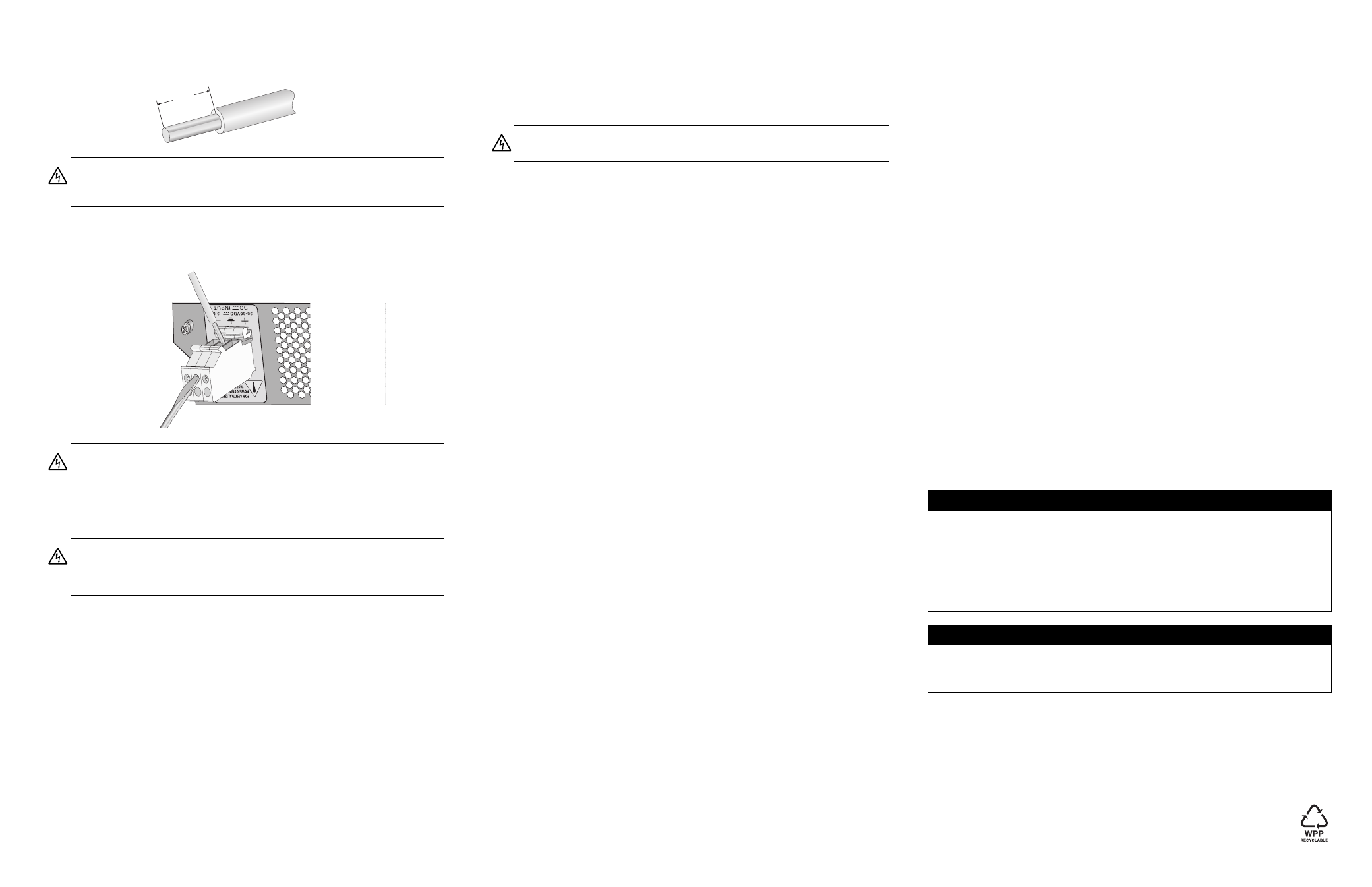
8.
With a 14-gauge wire-stripping tool, strip the three wires in the tray cable coming from
the DC input power source to 8 millimeters ± 1 millimeters (0.31 inches ± 0.039
inches), as shown below.
9.
Connect the frame ground wire to the terminal marked with the ground symbol by
inserting the wire into the terminal block and tightening the connection with a flathead
screwdriver, as shown below. .
10. Connect the positive feed wire to the terminal block marked + (positive).
11. Connect the negative feed wire to the terminal block marked - (negative).
12. Secure the tray cable near the rack framework using multiple cable ties (not
provided) to minimize the chance of the connections being disturbed by casual
contact with the wiring. Allied Telesis recommends that you use at least four cable
ties 10 centimeters (4 inches) apart with the first one located within 15 centimeters (6
inches) of the terminal block.
13. Ensure that the circuit breaker is in the Off position.
14. Connect the DC wires to the circuit breaker.
15. Power on the circuit breaker.
16. Verify that the Power LED is green. If it is not, refer to “Testing and Troubleshooting
the Installation.”
Hot Swapping an
AT-PWR9 Power Supply
This section describes how to replace a failed AT-PWR9 Power Supply in an AT-MCR12
chassis.
Note
Hot swapping requires that the main and auxiliary power supplies be connected to
separate DC circuits.
1.
Power off the appropriate DC circuit to the failed power supply.
2.
Remove the positive and negative feed wires from the terminal block by loosening
the screws to the wire connections with a flathead screwdriver.
3.
Remove the frame ground wire from the terminal block by loosening the screw to the
wire connection with a flathead screwdriver.
4.
Loosen the captive screws on the failed power supply and slide it out of the chassis.
5.
Slide a new power supply into the slot.
6.
Refer to “Installing an AT-PWR9 Power Supply as an Auxiliary Power Supply” for
information about installing and wiring the replacement power supply.
Testing and Troubleshooting the Installation
Follow the guidelines in this section for testing and troubleshooting the installation in the
event that a problem occurs.
1.
Verify that the Power, PWR A and PWR B LEDs are green. If one of the LEDs is
OFF, do the following:
Check to be sure that the power supply is securely connected to the power outlet.
Check to be sure that the power supply is securely seated in the chassis.
Check to be sure that the wires are connected to the correct terminals.
Check to be sure that the DC power circuit is powered ON.
2.
Check to be sure that the fans for both power supplies are operating. If a fan is not
operating, it is likely that the power supply has failed.
If you still have problems after testing and troubleshooting the installation, contact Allied
Telesis Technical Support at www.alliedtelesis.com for assistance.
Warranty Registration
Allied Telesis hardware products are covered under limited warranties. Some products
have a longer warranty coverage than others.
This AT-PWR9 power supply has a limited warranty of 5 years.
All Allied Telesis warranties are subject to the terms and conditions set out on the Allied
Telesis website at www.alliedtelesis.com/warranty.
Specifications
Physical Characteristics
Dimensions (H x W x L)
225 mm x 61 mm x 120 mm
(8.9 in x 2.4 in x 4.7 in)
Weight
.75 kg (1.65 lbs)
Operating Temperature
0° C to 40° C (32° F to 104° F)
Storage Temperature
-25° C to 70° C (-13° F to 158° F)
Operating Relative Humidity
5% to 90% RH (non-condensing)
Storage Relative Humidity
5% to 95% RH (non-condensing)
Power Requirements
Input Supply Voltage
36 to 72 V DC
Maximum Inrush Current
10 A maximum
Maximum Current
4 A at 48 V DC
Agency Certifications
Electrical Safety
UL60950-1 (
c
UL
us
), EN60950-1 (TUV),
CSA 950
Immunity
EN50082-1
Emission
EN55022-1 Class A
Electrical, Safety, and Emissions Statements
This product meets the following standards.
Copyright © 2007 Allied Telesis, Inc. All rights reserved. No part of this publication may
be reproduced without prior written permission from Allied Telesis, Inc.
Warning: Do not strip more than the recommended amount of wire. Stripping
more than the recommended amount can create a safety hazard by leaving
exposed wire on the terminal block after installation.
E10
Warning: When installing this equipment, always ensure that the frame ground
connection is installed first and disconnected last.
E11
Warning: Check to see if there are any exposed copper strands coming from the
installed wire. When this installation is done correctly there should be no exposed
copper wire strands extending from the terminal block. Any exposed wiring can
conduct harmful levels of electricity to persons touching the wires.
E12
8mm ±1mm
(0.31in. ±0.039in.)
Warning: When installing this equipment, always ensure that the frame ground
connection is installed first and disconnected last.
E11
U.S. Federal Communications Commission
Radiated Energy
Note: This equipment has been tested and found to comply with the limits for a Class A digital device
pursuant to Part 15 of FCC Rules. These limits are designed to provide reasonable protection
against harmful interference when the equipment is operated in a commercial environment. This
equipment generates, uses, and can radiate radio frequency energy and, if not installed and used
in accordance with this instruction manual, may cause harmful interference to radio
communications. Operation of this equipment in a residential area is likely to cause harmful
interference in which case the user will be required to correct the interference at his own expense.
Note: Modifications or changes not expressly approved of by the manufacturer or the FCC, can void
your right to operate this equipment.
Industry Canada
This Class A digital apparatus meets all requirements of the Canadian Interference-Causing
Equipment Regulations.
Cet appareil numérique de la classe A respecte toutes les exigences du Règlement sur le matériel
brouilleur du Canada.