Dip switch settings, Twisted pair port pinouts, Warranty information – Allied Telesis AT-CM70S Converteon Line Cards User Manual
Page 2: Specifications, Electrical safety and emissions statements, Fcc part 68 customer information
4
5
6
Twisted Pair Port LEDs
The twisted pair port has three LEDs, as described in the following table. For more
information about Smart MissingLink, refer to the relevant management software user’s
guide..
T1/E1 Port LEDs
Each T1/E1 port has four LEDs, as described in the following table.
DIP Switch Settings
The DIP switches as described in the following table allow you to set the operating mode
of the line card. For information about the operating modes as well as OAM, refer to the
relevant management software user’s guide.
“X” means that the DIP switch position can be ON or OFF.
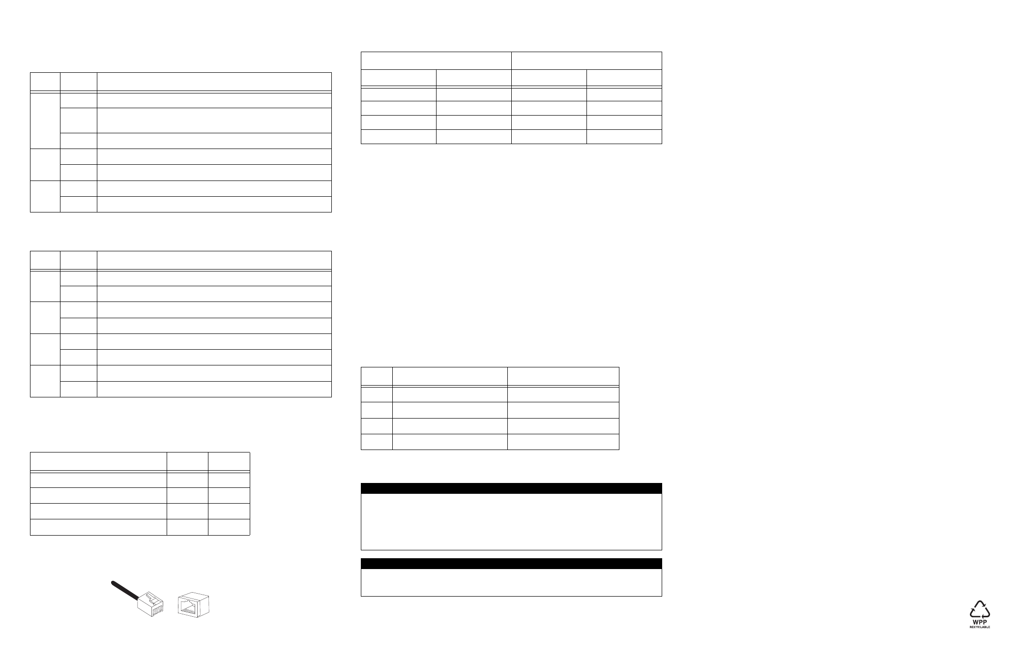
Twisted Pair Port Pinouts
The pinouts for the RJ-45 twisted pair port are shown in the following illustration.
The following table lists the RJ-45 pin signals when a twisted pair port is operating in the
MDI or MDI-X mode.
Warranty Information
The AT-CM70S line card has a limited warranty of five years. Go to
www.alliedtelesis.com/warranty for the specific terms and conditions of the warranty and
for warranty registration.
Specifications
Physical, Environmental, and Electrical Ratings
Dimensions (H x W x L)
(4.4 cm x 7.3 cm x 13.0 cm)
1.71 in. x 2.89 in. x 5.1 in.
Weight
0.54 kg (1.20 lbs.)
Operating Temperature
0° C to 40° C (32° F to 104° F)
Storage Temperature
-25° C to 70° C (-13° F to 158° F)
Operating Relative Humidity
5% to 90% (non-condensing)
Storage Relative Humidity
5% to 95% (non-condensing)
Operating Altitude Range
Up to 3,048 m (10,000 ft.)
Predicted MTBF (Telcordia SR332)
670,000 hours
Power Consumption
8.5 Watts
T1/E1 TDM Port Pin Signals
The pin signals for the T1/E1 TDM ports are listed in the following table.
Electrical Safety and Emissions Statements
This product meets the following standards when installed in compliant host equipment.
Emissions
FCC Class A, EN55022 Class A, VCCI Class A, C-TICK, CE
Warning: In a domestic environment this product may cause radio interference in which
case the user may be required to take adequate measures.
Immunity
EN55024
Electrical Safety
UL60950 (
c
UL
us
), EN60950 (TUV), CSA22.2 No. 950
FCC Part 68 Customer Information
a) This equipment complies with Part 68 of the FCC rules and the requirements
adopted by the ACTA. On the side plate of the chassis of this equipment is a label
that contains, among other information, a product identifier in the format
US:AAAEQ##TXXXX. If requested, this number must be provided to the telephone
company.
b) The following are required when the customer orders service from the local
telephone company:
Universal Service Order Codes ("USOC") for the Equipment: RJ48C
Facility Interface Code ("FIC"): 04DU9.1SN
Service Order Code ("SOC"): 6.0N
c)
A plug and jack used to connect this equipment to the premises wiring and telephone
network must comply with the applicable FCC Part 68 rules and requirements
adopted by the ACTA. A compliant telephone cord and modular plug is provided with
this product. It is designed to be connected to a compatible modular jack that is also
compliant. See installation instructions for details.
d) If this equipment, model AT-CM70S causes harm to the telephone network, the
telephone company will notify you in advance that temporary discontinuance of
service may be required. But if advance notice isn't practical, the telephone company
will notify the customer as soon as possible. Also, you will be advised of your right to
file a complaint with the FCC if you believe it is necessary.
e) The telephone company may make changes in its facilities, equipment, operations or
procedures that could affect the operation of the equipment. If this happens the
telephone company will provide advance notice in order for you to make necessary
modifications to maintain uninterrupted service.
f)
If trouble is experienced with this equipment model AT-CM70S, for repair or warranty
information, please contact:
Allied Telesis Inc.
Technical Support
19800 North Creek Parkway, Suite 200
Bothell, WA 98011
1-800-428-4835
www.alliedtelesis.com
If the equipment is causing harm to the telephone network, the telephone company
may request that you disconnect the equipment until the problem is resolved.
g) This product is not intended to be repaired by the customer (user).
h) Connection to party line service is subject to state tariffs. Contact the state public
utility commission, public service commission or corporation commission for
information.
i)
If your home has specially wired alarm equipment connected to the telephone line,
ensure the installation of this US: A5TDWNANAT-CM70S does not disable your
alarm equipment. If you have question about what will disable alarm equipment,
consult your telephone company or a qualified installer.
Copyright © 2007 Allied Telesis, Inc. All rights reserved.
No part of this publication may be reproduced without prior written permission from Allied
Telesis, Inc.
LED
State
Description
L/A
Green
A link has been established on the port.
Blinking
Green
While in Smart MissingLink mode, a valid connection is established
on the port while a link on the other port is lost.
Off
No link has been established on the port.
FD
Green
The port is operating in full-duplex mode.
Off
The port is operating in half-duplex mode.
100
Green
The port is operating at 100 Mbps.
Off
The port is operating at 10 Mbps.
LED
State
Description
RCL
Amber
Receive carrier loss occurred.
Green
The port is operating normally.
LOTC
Amber
Loss of transmit clock occurred.
Green
The port is operating normally.
AIS
Amber
Port received unframed all ones.
Green
The port is operating normally.
TEST
Amber
Port synchronized to test stream.
Green
The port is operating normally.
Operating Mode
DIP 1
DIP 2
Link Test (non-OAM)
OFF
X
OAM Bypass
ON
OFF
OAM Visible
ON
ON
Manufacturing Default Settings
OFF
OFF
8
8
1
1
MDI Mode
MDI-X Mode
Pin
Signal
Pin
Signal
1
TX+
1
RX+
2
TX-
2
RX-
3
RX+
3
TX+
6
RX-
6
TX-
Pin
Signal
Description
1
Receive Ring (RX, Ring-)
Input to AT-CM70S
2
Receive Tip (TX, Tip+)
Input to AT-CM70S
4
Transmit Ring (TX, Ring-)
Output from AT-CM70S
5
Transmit Tip (TX, Tip+)
Output from AT-CM70S
U.S. Federal Communications Commission
Radiated Energy
Note: This equipment has been tested and found to comply with the limits for a Class A digital device pursuant to
Part 15 of FCC Rules. These limits are designed to provide reasonable protection against harmful interference when
the equipment is operated in a commercial environment. This equipment generates, uses, and can radiate radio
frequency energy and, if not installed and used in accordance with this instruction manual, may cause harmful
interference to radio communications. Operation of this equipment in a residential area is likely to cause harmful
interference in which case the user will be required to correct the interference at his own expense.
Note: Modifications or changes not expressly approved of by the manufacturer or the FCC, can void your right to
operate this equipment.
Industry Canada
This Class A digital apparatus meets all requirements of the Canadian Interference-Causing Equipment
Regulations.
Cet appareil numérique de la classe A respecte toutes les exigences du Règlement sur le matériel brouilleur du
Canada.