Dip switch settings, Twisted pair port pinouts, Warranty information – Allied Telesis AT-CM2K0S User Manual
Page 2: Specifications, Electrical safety and emissions statements
4
5
6
* When the 1000M and 100M LEDs are both off, the port is operating at 10 Mbps.
DIP Switch Settings
The DIP switches as described in the following table allow you to set the operating mode
of the line card. For information about the operating modes as well as Smart MissingLink,
MissingLink, and OAM, refer to the relevant management software user’s guide.
“X” means that the DIP switch position can be ON or OFF.
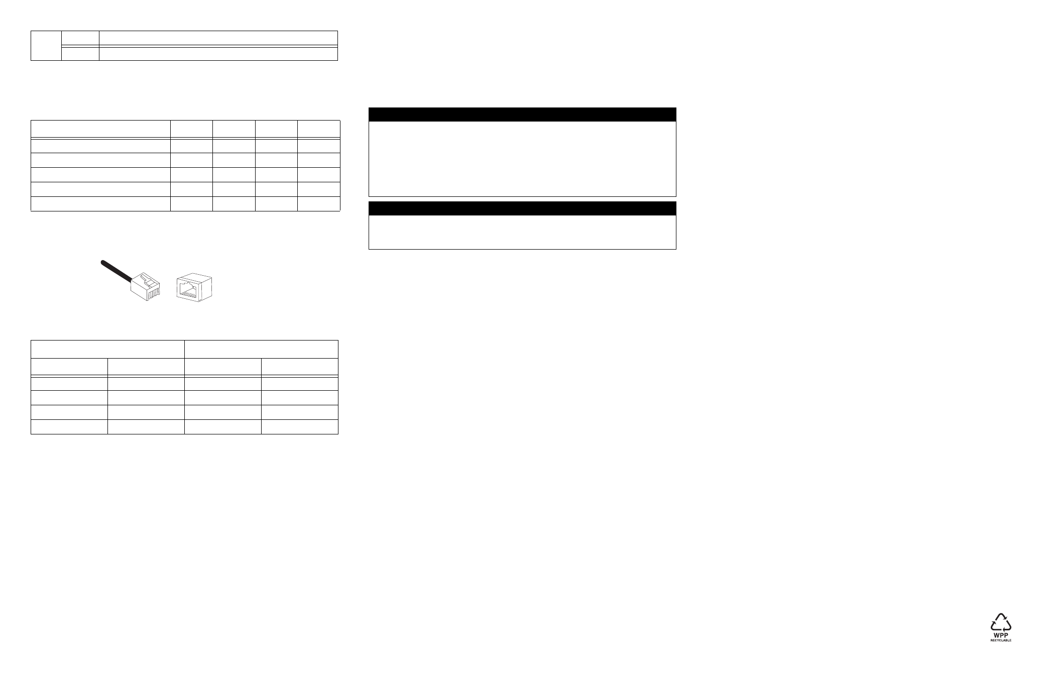
Twisted Pair Port Pinouts
The pinouts for the RJ-45 twisted pair port are shown in the following illustration.
The following table lists the RJ-45 pin signals when a twisted pair port is operating in the
MDI or MDI-X mode.
Warranty Information
The AT-CM2K0S line card has a limited warranty of five years. Go to
www.alliedtelesis.com/warranty for the specific terms and conditions of the warranty and
for warranty registration.
Specifications
Physical, Environmental, and Electrical Ratings
Dimensions (H x W x L)
(2.2 cm x 7.3 cm x 13.0 cm)
.78 in. x 2.89 in. x 5.1 in.
Operating Temperature
0° C to 40° C (32° F to 104° F)
Storage Temperature
-25° C to 70° C (-13° F to 158° F)
Operating Relative Humidity
5% to 90% (non-condensing)
Storage Relative Humidity
5% to 95% (non-condensing)
Operating Altitude Range
Up to 3,048 m (10,000 ft.)
Predicted MTBF (Telcordia SR332)
880,000 hours
Power Consumption
6.5 Watts maximum
Electrical Safety and Emissions Statements
This product meets the following standards when installed in compliant host equipment.
Emissions
FCC Class A, EN55022 Class A, VCCI Class A, C-TICK, CE
Warning: In a domestic environment this product may cause radio interference in which
case the user may be required to take adequate measures.
Immunity
EN55024
Electrical Safety
UL60950 (
c
UL
us
), EN60950 (TUV), CSA22.2 No. 950
Copyright © 2008 Allied Telesis, Inc. All rights reserved.
Off
The port is not operating at 100 Mbps.*
Operating Mode
DIP 1
DIP 2
DIP 3
DIP 4
Link Test (default)
OFF
OFF
OFF
X
Smart MissingLink (SML)
OFF
ON
ON
X
MissingLink (ML)
OFF
OFF
ON
X
OAM Bypass
ON
OFF
OFF
X
OAM Visible
ON
ON
OFF
X
MDI Mode
MDI-X Mode
Pin
Signal
Pin
Signal
1
TX+
1
RX+
2
TX-
2
RX-
3
RX+
3
TX+
6
RX-
6
TX-
LED
State
Description
8
8
1
1
U.S. Federal Communications Commission
Radiated Energy
Note: This equipment has been tested and found to comply with the limits for a Class A digital device
pursuant to Part 15 of FCC Rules. These limits are designed to provide reasonable protection against
harmful interference when the equipment is operated in a commercial environment. This equipment
generates, uses, and can radiate radio frequency energy and, if not installed and used in accordance
with this instruction manual, may cause harmful interference to radio communications. Operation of
this equipment in a residential area is likely to cause harmful interference in which case the user will
be required to correct the interference at his own expense.
Note: Modifications or changes not expressly approved of by the manufacturer or the FCC, can void
your right to operate this equipment.
Industry Canada
This Class A digital apparatus meets all requirements of the Canadian Interference-Causing
Equipment Regulations.
Cet appareil numérique de la classe A respecte toutes les exigences du Règlement sur le matériel
brouilleur du Canada.