Leds, Port specifications, Technical specifications – Allied Telesis AT-A47 Expansion Modules User Manual
Page 2: Electrical safety and emission statement, Pin signal, Class 1 laser p roduct do not stare into be am
6. Remove the faceplate from the slot.
Keep the faceplate in a safe area in case you need to install it in the slot
again. The faceplate will keep any dust from getting into the switch and
will maintain proper airflow if the slot remains empty.
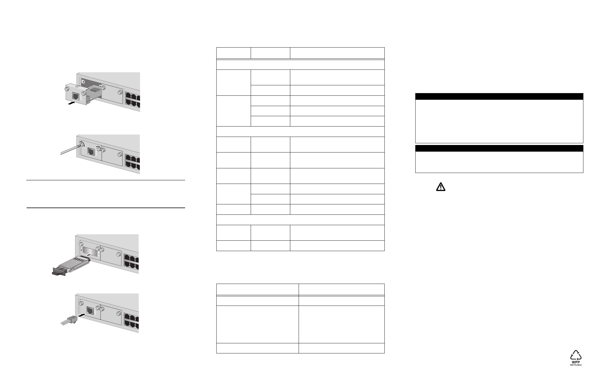
7. Carefully slide the expansion module into the slot until the expansion
module faceplate makes contact with the switch, as displayed below.
Avoid touching the expansion module components.
8. Secure the expansion module to the switch by using a Phillips screwdriver
to tighten the installation screws found on the expansion module faceplate.
Note
Always use the installation screws to secure the expansion module to the
switch. Leaving an expansion module partially seated may cause the
system to halt and subsequently crash.
9. If you purchased an AT-A47 expansion module, slide the GBIC module
into the slot on the expansion module until it snaps into place, as displayed
below.
10. Connect the twisted pair or fiber optic data cable to the expansion module.
11. Make sure the LINK LED on the front of the expansion module is steady
green. (A 1000Base port may require from five to ten seconds to initially
establish a link with an end node.)
26
1
3
5
2
4
6
25
10/100/1
000BASE-T
AT-A46
10
100
FULL
DUPLEX
ACTIVITY
LINK
1000
26
1
3
5
2
4
6
25
10/100/1
000B
ASE-T
AT-A46
10
100
FULL DUPLEX
ACTIVITY
LINK
1000
26
1
3
5
2
4
6
25
1000B
ASE-X
AT-A47
10
ACTIVITY
LINK
CLASS 1
LASER P
RODUCT
DO NOT
STARE
INTO BE
AM
26
1
3
5
2
4
6
25
10/100/1
000B
ASE-T
AT-A46
10
100
FULL DUPLEX
ACTIVITY
LINK
1000
LEDs
The expansion modules have port LEDs which display link and activity status
on the port. Refer to the table below for port LED information.
Port Specifications
The table below provides port specifications for the AT-A45/MT and AT-A45/
SC expansion modules.
LED
State
Description
AT-A45/xx Series Expansion Modules
LINK
Steady Green
The port has established a valid link with the
end node.
Flashing Green
The port is transmitting and/or receiving data.
DUPLEX
Steady Green
The port is operating in full-duplex.
Steady Amber
The port is operating in half-duplex.
Flashing Amber
Collisions are occurring on the port.
AT-A46 Expansion Module
LINK 10
Steady Green
The port has established a valid
10 Mbps link with the end node.
LINK 100
Steady Green
The port has established a valid
100 Mbps link with the end node.
Both LINK 10
and LINK 100
Steady Green
The port has established a valid
1000 Mbps link with the end node.
FULL
DUPLEX
Steady Green
The port is operating in full-duplex.
OFF
The port is operating in half-duplex.
ACTIVITY
Flashing Green
The port is transmitting and/or receiving data.
AT-A47 Expansion Module
LINK
Steady Green
The port has established a valid 1000 Mbps
link with the end node.
ACTIVITY
Flashing Green
The port is transmitting and/or receiving data.
Pin
Signal
Operating Wavelength
1310 nm
Transmitter Output Power
50/125 µm cabling
Min: -22.5 dBm avg.
Max: -14 dBm avg.
62.5/125 µm cabling
Min: -19 dBm avg.
Max: -14 dBm avg.
Receiver Sensitivity
Max: -14 dBm avg.
Technical Specifications
Operating Temperature
0° C to 40° C (32° F to 104° F)
Storage Temperature
-20° C to 80° C (-4° F to 176° F)
Operating Relative Humidity
Up to 3,048 meters (10,000 feet)
Storage Relative Humidity
5% to 80% (non-condensing)
Electrical Safety and Emission Statement
Standards: This product meets the following standards when installed in compliant host equipment.
Emission
FCC Class A, EN55022 Class A, VCCI Class A
WARNING:
In a domestic environment this product may cause radio interference in which
case the user may be required to take adequate measures.
Immunity
EN55024
Electrical Safety
UL60950-1 (
c
UL
us
), EN60950-1 (TUV)
Copyright
© 2008 Allied Telesis, Inc. All rights reserved.
No part of this publication may be reproduced without prior written permission from Allied Telesis Inc.
U.S. Federal Communications Commission
RADIATED ENERGY
Note: This equipment has been tested and found to comply with the limits for a Class A digital device pursuant
to Part 15 of FCC Rules. These limits are designed to provide reasonable protection against harmful
interference when the equipment is operated in a commercial environment. This equipment generates, uses,
and can radiate radio frequency energy and, if not installed and used in accordance with this instruction
manual, may cause harmful interference to radio communications. Operation of this equipment in a residential
area is likely to cause harmful interference in which case the user will be required to correct the interference at
his own expense.
Note: Modifications or changes not expressly approved of by the manufacturer or the FCC, can void your right
to operate this equipment.
Industry Canada
This Class A digital apparatus meets all requirements of the Canadian Interference-Causing Equipment
Regulations.
Cet appareil numérique de la classe A respecte toutes les exigences du Règlement sur le matériel brouilleur
du Canada.
4
5
6