Allied Telesis Removable Power Supply and Fan User Manual
Page 17
Removable Power Supply and Fan
16
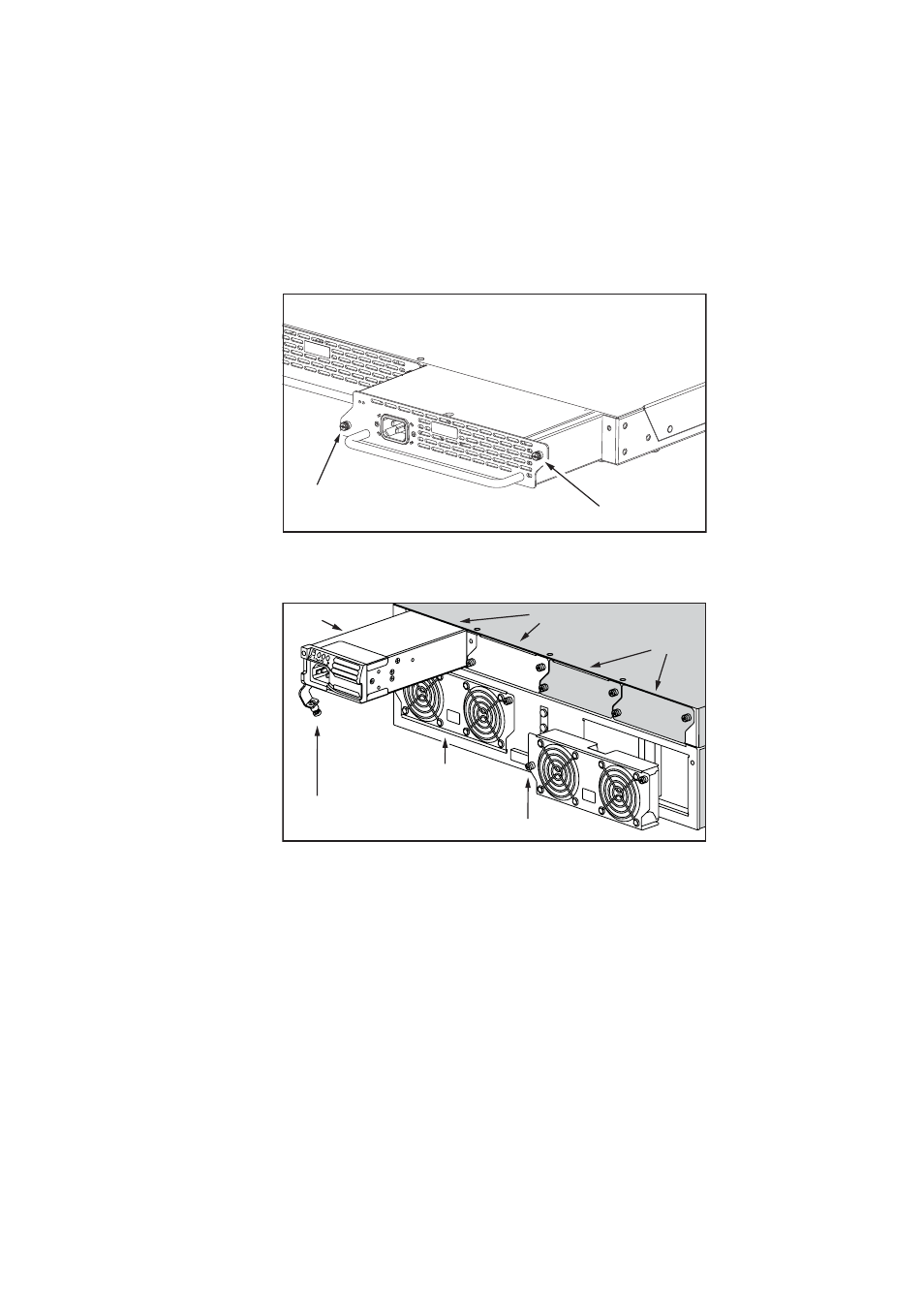
The following is a diagram of PWR05 and FAN03
3.
Remove the PSU, chassis fan module, FOM or the blanking plate from the
switch.
Slide the unit out slowly and carefully. Support the unit from underneath as
you remove it, to prevent it from falling.
4.
For all units, with the exception of FAN03, cover empty bays with a
blanking plate, to prevent dust and debris from overheating or damaging the
switch.
Captive screw
Captive screw
PSU
Switch
Captive screw
PSU bays
PSU
Captive screw
Chassis fan
Service
access
panels
See also other documents in the category Allied Telesis Computer hardware:
- AT-GS908M (54 pages)
- AT-x230-10GP (80 pages)
- AT-GS950/48PS (64 pages)
- AT-GS950/10PS (386 pages)
- AT-GS950/16PS (386 pages)
- AT-GS950/48PS (386 pages)
- AT-9000 Series (1480 pages)
- AT-9000 Series (258 pages)
- IE200 Series (70 pages)
- AT-GS950/48 (410 pages)
- AT-GS950/8 (52 pages)
- AT-GS950/48 (378 pages)
- AT-GS950/48 (60 pages)
- SwitchBlade x8106 (322 pages)
- SwitchBlade x8112 (322 pages)
- SwitchBlade x8106 (240 pages)
- SwitchBlade x8112 (240 pages)
- AT-TQ Series (172 pages)
- AlliedWare Plus Operating System Version 5.4.4C (x310-26FT,x310-26FP,x310-50FT,x310-50FP) (2220 pages)
- FS970M Series (106 pages)
- 8100L Series (116 pages)
- 8100S Series (140 pages)
- x310 Series (120 pages)
- x310 Series (116 pages)
- AT-GS950/24 (404 pages)
- AT-GS950/24 (366 pages)
- AT-GS950/16 (44 pages)
- AT-GS950/16 (404 pages)
- AT-GS950/16 (364 pages)
- AT-GS950/8 (404 pages)
- AT-GS950/8 (364 pages)
- AT-GS950/8 (52 pages)
- AT-8100 Series (330 pages)
- AT-8100 Series (1962 pages)
- AT-FS970M Series (330 pages)
- AT-FS970M Series (1938 pages)
- SwitchBlade x3106 (288 pages)
- SwitchBlade x3112 (294 pages)
- SwitchBlade x3106 (260 pages)
- SwitchBlade x3112 (222 pages)
- AT-S95 CLI (AT-8000GS Series) (397 pages)
- AT-S94 CLI (AT-8000S Series) (402 pages)
- AT-IMC1000T/SFP (23 pages)
- AT-IMC1000TP/SFP (24 pages)
- AT-SBx3106WMB (44 pages)