Technical specifications, Electrical safety and emission statement – Allied Telesis AT-PWR3004 User Manual
Page 2
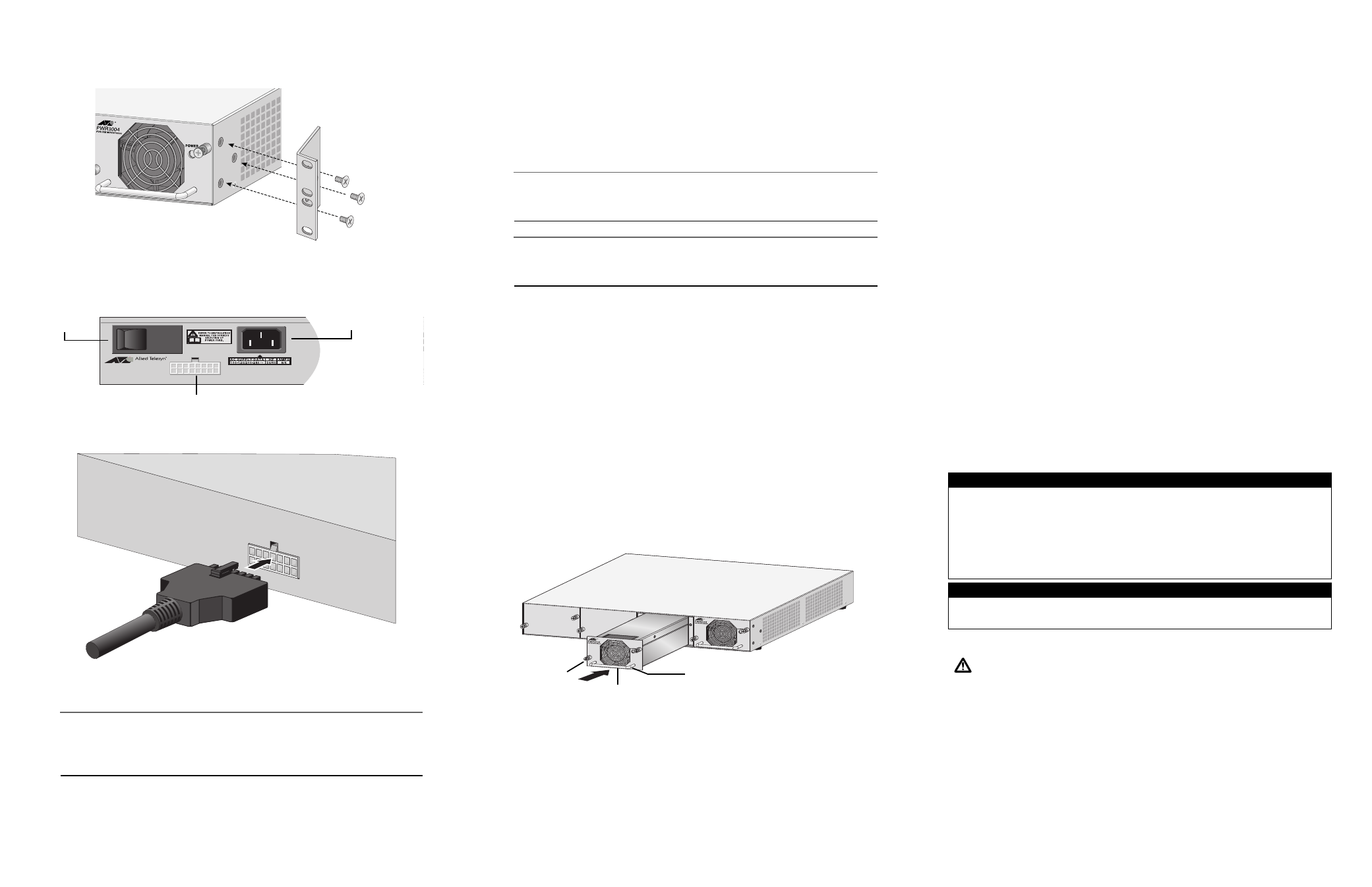
4. Attach the two rackmounting brackets to each side of the power supply chassis
using the six screws that came with the RPS chassis, as displayed below.
5. Mount the power supply in the 19-inch rack using standard screws (not provided).
6. Attach the provided DC power cord to the DC connector on the back panel of the
AT-RPS3004 power supply.
7. Connect the other end of the DC power cord to the RPS Input connector on the
back panel of the Ethernet switch.
8. Plug the AC power cord for the AT-RPS3004 into the AC connector on the back
panel of the unit.
Note
The AT-RPS3004 unit and Ethernet switches should be connected to power
outlets on separate circuits. This will protect the switches from a loss of power
should the switch circuit breaker trip.
9. Plug the other end of the AC power cord into a wall outlet.
AT-PWR3004
ON/OFF
Switch
DC Connector
AC Power
Connector
10. Turn on the AT-RPS3004 unit using the switch on the back panel of the unit.
11. Make sure the LED on the front of the power supply is solid green.
12. Make sure the RPS LED on the front of the Ethernet switch is green. This indicates
a good connection to the AT-RPS3004 unit.
Installing an Additional AT-PWR3004 Power Supply Module
Note
The AT-PWR3004 power module must be installed in an AT-RPS3004 chassis.
It cannot be used as a standalone unit.
Note
It is not necessary to power OFF the AT-RPS3004 unit or the connected Ethernet
switches to install a new AT-PWR3004 power module.
To install an additional AT-PWR3004 power module, perform the following steps:
1. Remove the AT-PWR3004 power module from the shipping package and store
the packing material in a safe place.
2. Remove a blank faceplate from an empty expansion slot from the front of the AT-
RPS3004 unit by unscrewing the two installation screws with a Phillips
screwdriver.
3. Before installing the new AT-PWR-3004 power module, identify the DC power
connector on the back panel of the AT-RPS3004 unit directly behind the power
module slot where the new power module will be installed and attach one end of
the provided DC power cord to this DC connector.
4. Attach the other end of the DC power cord to the RPS Input connector on the back
panel of the Ethernet switch.
5. Place one hand under the AT-PWR3004 power module to support it and place the
other hand on the handle. Slide the new AT-PWR3004 power module into the
chassis, as displayed below, to guide the module into the unit.
6. Once firmly installed, use a Phillips screwdriver to tighten the installation screws
on the module to secure it to the chassis.
7. Make sure the LED on the front of the AT-PWR3004 power module is green.
8. Make sure the RPS LED on the front of the Ethernet switch is green. This indicates
a good connection to the AT-PWR3004 power module.
Installation
Handle
Installation Screw
Screw
Technical Specifications
Dimensions:
AT-RPS3004 Unit:
44 cm x 35.56 cm x 6.6 cm
(17.32 in x 14 in x 2.6 in)
AT-PWR3004 Power Module:
30.48 cm x 10.8 cm x 6.35 cm
(12 in x 4.25 in x 2.5 in)
Weight:
AT-RPS3004 Fully Loaded:
9.46 kg (20.85 lb)
AT-PWR3004 Power Module:
1.06 kg (2.35 lb)
Input Voltage:
100 to 264 VAC
Input Frequency Range:
50 to 60 Hz
Maximum Operating Temperature:
-20° C to 40° C (-4° F to 104° F)
Maximum Storage Temperature:
-40° C to 70° C (-40° F to 158° F)
Operating and Storage Altitude:
Up to 3,048 meters (10,000 ft)
Humidity:
8% to 95% (non-condensing)
EMC:
FCC Class A,
EN55022 Class A, EN55024
Safety:
EN60825, EN60950 (TUV),
UL1950 (UL/cUL)
Electrical Safety and Emission Statement
Standards: This product meets the following standards.
Emission
FCC Class A, EN55022 Class A, VCCI Class A
WARNING:
In a domestic environment this product may cause radio interference in which case the user may
be required to take adequate measures.
Immunity
EN55024
Electrical Safety
UL1950 (UL/cUL), EN60950 (TUV)
Copyright
© 2009 Allied Telesis, Inc. All rights reserved.
No part of this publication may be reproduced without prior written permission from Allied Telesis, Inc.
U.S. Federal Communications Commission
RADIATED ENERGY
Note: This equipment has been tested and found to comply with the limits for a Class A digital device pursuant to Part 15
of FCC Rules. These limits are designed to provide reasonable protection against harmful interference when the
equipment is operated in a commercial environment. This equipment generates, uses, and can radiate radio frequency
energy and, if not installed and used in accordance with this instruction manual, may cause harmful interference to radio
communications. Operation of this equipment in a residential area is likely to cause harmful interference in which case
the user will be required to correct the interference at his own expense.
Note: Modifications or changes not expressly approved of by the manufacturer or the FCC, can void your right to operate
this equipment.
Industry Canada
This Class A digital apparatus meets all requirements of the Canadian Interference-Causing Equipment Regulations.
Cet appareil numérique de la classe A respecte toutes les exigences du Règlement sur le matériel brouilleur du Canada.
4
5
6