Allied Telesis AT-8000S (Layer 2) User Manual
Page 18
Page 18
Allied Telesis AT-8000SSwitch
Switch Installation Guide
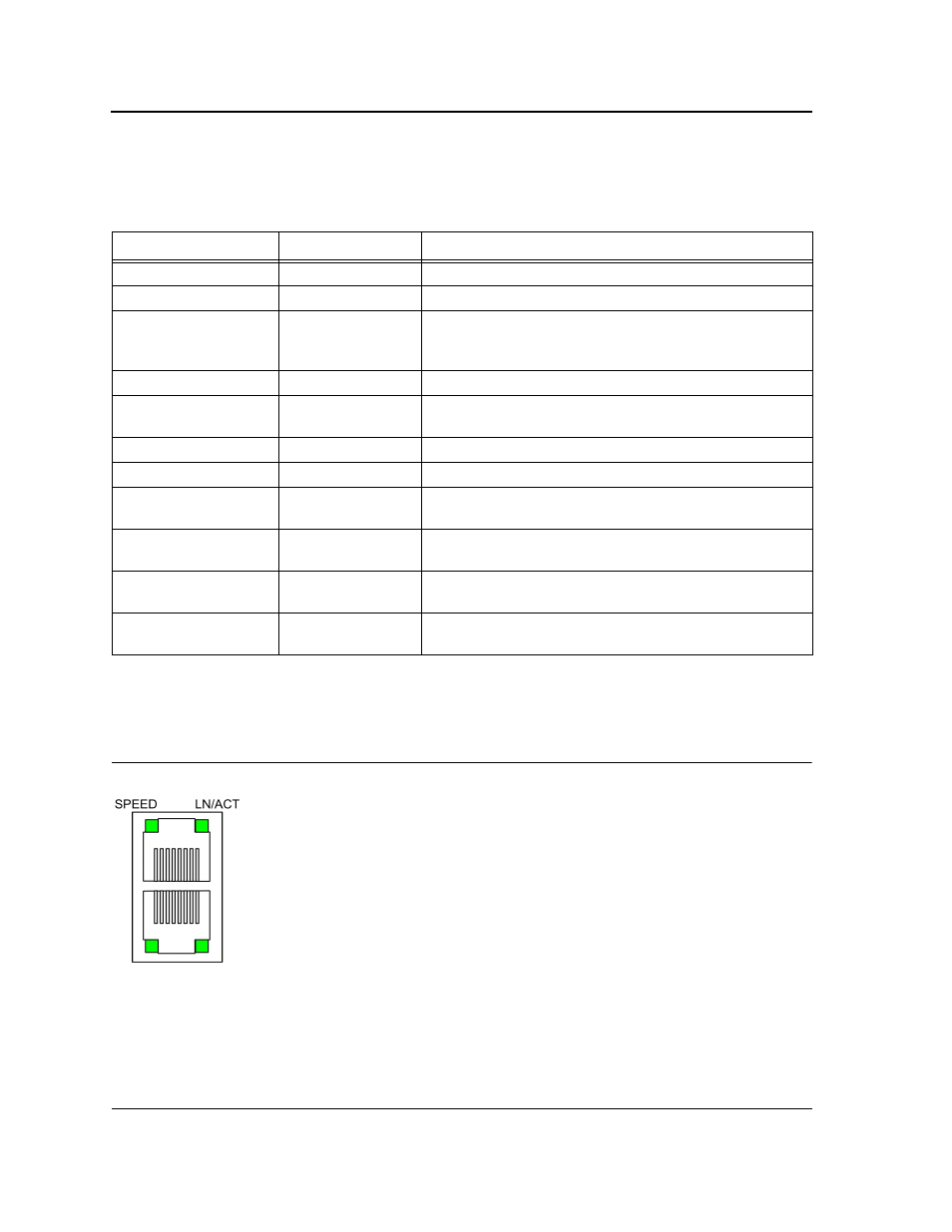
The RJ-45 ports have two LEDs, one for Link and one for activity (Mode status for non PoE and Load status for
PoE). The LED indications are described in the following table:
10/100/1000 Base-T/Combo Ethernet RJ-45 Port LEDs
The following figure illustrates the 10/100/1000 Base-T/Combo Ethernet RJ-45 port LEDs.
Figure 14: 10/100/1000 Base-T/Combo Ethernet RJ-45 Port LEDs
Table 3:
10/100Base-T Fast Ethernet RJ-45 Port LED Indications
Port Description
LED Indication
Description
Left LED - Link
Green
A 100-Mbps link is established on the port.
Off
No link is established on the link.
Right LED - Mode
Green
This indication is determined by the mode selected. For
example if the mode SPD is selected, and the port mode
LED is green, there is a link established at 100Mbps.
Off
This indication is determined by the mode selected.
Left LED (PoE model) -
Link / Act
Green
A link is established on the port.
Flashing green
Port is transmitting and/or receiving data.
Off
No link is established on the port.
Right LED - POE (PoE
model)
Green
The port detects a Power Device (PD) and complies with the
condition of a normal load.
Amber
An overload, a terminal short or external forced voltage
feeds into the port.
Flashing amber
The port detects a PD but the power provided to it exceeds
the maximum POE power budget of the switch.
Off
No PD is connected, and subsequently there is no power
feeding.