Warning, Wiring diagrams (cont.), Gas range controls – Samsung NX58H5650WS-AA User Manual
Page 2: Warming drawer servicing, Failure code chart, Cooktop servicing, Oven servicing
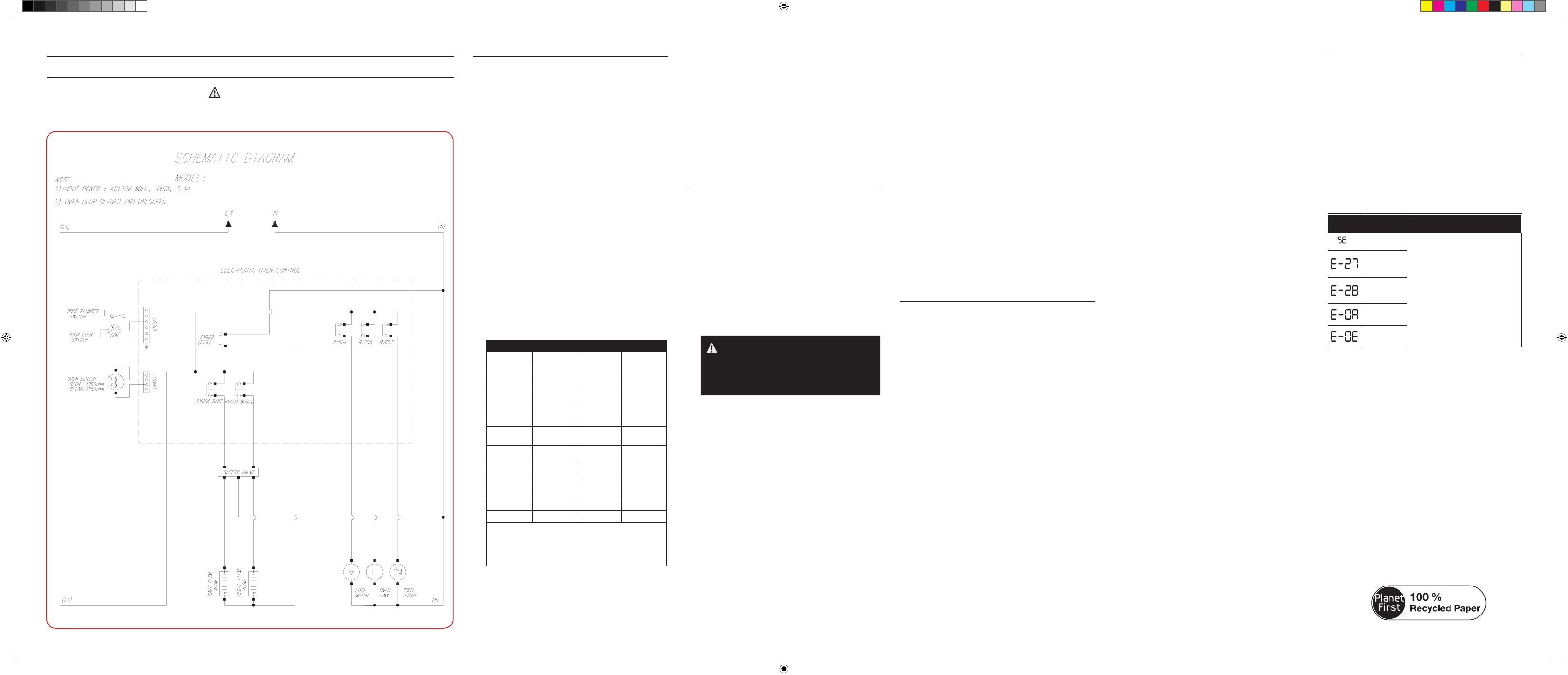
WIRING DIAGRAMS (CONT.)
Model NX58H5600SS
WARNING
POWER MUST BE DISCONNECTED BEFORE SERVICING THIS APPLIANCE.
NX58H5600SS
GAS RANGE CONTROLS
1. Calibrating the oven temperature
The oven temperature can be calibrated to meet your
cooking needs and/or match your previous oven
temperature settings.
A. Remove the warming drawer or the storage drawer.
B. Locate the pressure regulator in the left-rear of the
drawer opening.
C. Using your fingers, turn the red cap and the dual-
purpose orifice counterclockwise to remove them from
the pressure regulator.
D. Remove the cap from the orifice and reinstall it on the
opposite side of the orifice.
E. Reinstall the orifice in the pressure regulator so the
large open LP gas end is exposed. Tighten the orifice
until it is finger-tight. Do not overtighten. Make sure
the red cap is secured over the end of the orifice.
F. Make sure the gas shut-off lever on the side of the
pressure regulator is in the open position.
G. Replace the warming drawer or the storage drawer.
2. Accessing the oven control panel
A. Disconnect or turn off the electrical supply to the range.
B. Shut off the gas shut-off valve to the range.
C. Carefully pull range away from back wall to access the
cover-back guard Wire.
D. Remove the upper rear cover panel.
3. Testing the printed circuit board (PCB)
A. Carefully reconnect the electrical power and perform
the following checks.
B. After checks have been made, disconnect the power to
the range.
RELAY CONTACT OPERATION TEST
RELAY
TERMINALS
VOLTAGE IN
COOK MODE
VOLTAGE IN
OFF
Convection
bake
Conv. Bake
to N
120 VAC**
0 VAC
Convection
roast
Conv. Roast
to N
120 VAC**
0 VAC
Warming
drawer*
Warming
Dwr to N
0 VAC (in
Self-Clean)
120 VAC
Favorite
Cook
Cooking
Cycle to N
120 VAC
0 VAC
Self-clean
Self-Clean
to N
120 VAC
0 VAC
Bake
Bake to N
120 VAC**
0 VAC
Broil
Broil to N
120 VAC**
0 VAC
Keep Warm
Warm to N
120 VAC
0 VAC
Bread Proof
Proof to N
120 VAC
0 VAC
Oven light
Light to L1
120 VAC
0 VAC
*NX58H5650WS only
**Be sure to select a temperature or setting.
**120 VAC to Bake and Cook Time only.
Remaining circuits are deactivated until Sabbath
circuit is deactivated.
4. Replacing the PCB
A. Mark and disconnect the wires going to the PCB.
B. Remove 17 screws and cover wire LT/RT, cover-
back guard wire, cover-back main wire, and cover-
convection.
WARMING DRAWER SERVICING
(Model NX58H5650WS)
1. Warming drawer element replacement
A. Disconnect the electrical power to the range.
B. Shut off the gas supply to the range.
C. Pull out the warming drawer. Press down the left glide
lever, lift up on the right glide lever, and then remove
the drawer from the drawer opening.
D. Disconnect the connector from the back wall of the
warming drawer opening.
E. Remove the bottom screw and the heater-warming
drawer from the back wall of the warming drawer
opening.
F. Reverse the order to install and connect the new heater
warming drawer.
FAILURE CODE CHART
FAILURE
CODE
CAUSE
SOLUTION
Shorted Key.
Press the OFF/CLEAR pad and restart
the oven.
If the problem persists, disconnect
all power to the range for at least 30
seconds and then reconnect the power.
If this does not solve the problem, call
for service. See bottom of this chart.
Oven sensor
opened
problem.
Oven sensor
shorted
problem.
Oven
overheating.
Door locking
error.
DG68-00528A-00
C. Remove 2 screws from the Holder-PCB.
D. Replace the PCB and secure with 2 screws.
E. Reconnect all wires from where they were removed.
5. Spark module replacement
The spark module is located behind the upper rear cover
panel on the lower-right side.
A. Mark and disconnect the wires going to the spark
module.
B. Remove 2 screws and the spark module from the
backguard.
C. Install new spark module in the backguard and secure
with 2 screws.
D. Reconnect wires from where they were removed.
COOKTOP SERVICING
1. Removing the cooktop
A. Disconnect electrical power to the range.
B. Shut off the gas shut-off valve in the gas supply line to
the range.
C. Open the door or remove it.
D. Pull burner control knobs straight off to remove them
from the valve shafts.
E. Remove 2 screws from the top, 2 screws from the front
and 4 screws from the bottom of the chassis manifold
panel.
F. Remove the chassis manifold panel from the front of
the range.
G. Place a finger behind each side of the switch ignition
and pull it straight out to release it from the control
shaft. Repeat for each switch.
H. Disconnect the wires at the connectors.
2. Door latch replacement
A. Remove the oven door and the cooktop frame as
described above.
B. Remove the control knob and the chassis manifold.
C. Remove the Assy’ tube-manifold with a wrench.
D. Remove 2 screws from the Bracket-Latch sub to the
rear of the range.
E. Disconnect wires of the door latch to the rear of the
range and remove it.
F. Remove 2 screws holding the Assy bracket-latch rear
to the rear of the range.
G. Remove the latch-rod from the Assy bracket-latch front.
H. Remove 2 screws holding the Assy bracket-latch front
to the front of cavity.
I. After replacement, reverse the order to install the ASSY
DOOR LATCH.
3. Electrode/harness replacement
A. Remove cooktop as described above.
B. Remove the cover wire LT/RT and cover-back guard wire.
C. Carefully remove electrode locking clips from the bottom
of the electrodes on the burner cups. Lift and slide the
electrode wire out of the slot on the burner cup.
WARNING
Do not bend the aluminum tubing to the surface
burner cups. Bending can damage the tubing or
fittings resulting in death, personal injury, fire,
and/or product damage.
D. Trace electrode wire back to the starter module and
disconnect the wire from the spark module.
E. Connect new electrode harness to the spark module
in the same location from where the old harness was
removed.
F. Insert electrode in the slot in the burner cup and secure
it in place with the locking clip.
4. Ignition switch harness replacement
A. Disconnect electrical power to the range.
B. Shut off the gas shut-off valve in the gas supply line to
the range.
C. Open the door or remove it.
D. Pull burner control knobs straight off to remove them
from the valve shafts.
E. Remove 2 screws from the top, 2 screws from the front
and 4 screws from the bottom of the chassis manifold
panel.
F. Remove the chassis manifold panel from the front of
the range.
G. Place a finger behind each side of the switch ignition
and pull it straight out to release it from the control
shaft. Repeat for each switch.
H. Disconnect the wires at the connectors.
I. Connect the new ignition switch harness to the wire
connectors from where the old harness was removed
and install the new harness in reverse order.
OVEN SERVICING
1. Oven temperature sensor replacement
A. Disconnect electrical power to the range.
B. Open the oven door and remove the oven racks.
C. Disconnect connector of the sensor thermister to the
rear of the range.
D. Remove 2 screws securing the oven temperature
sensor to the upper left-hand corner of the rear wall.
E. Carefully pull out the sensor wire leads until the wire
connectors appear. NOTE: If the wire connectors
cannot be accessed from inside the oven, remove the
upper rear cover panel, mark the wires, and disconnect
them from behind the oven.
F. Reverse the order to install a new oven temperature
sensor.
2. Lower burner replacement (bake)
A. Turn off the electrical supply going to the range.
B. Shut off the gas shut-off valve in the gas supply line to
the range.
C. Open the oven door and remove the racks from inside
the oven.
D. Pull on the wires or the connector until the wire
connector appears from the back wall of the warming
drawer opening.
E. Disconnect the connector of HSI of the burner bake.
F. Remove the two screws from the back of the cavity
floor. Lift back to clear the front edge and lift out the
cavity floor.
G. Remove 2 screws from the front of the bracket bake-
spreader.
H. Lift front the bracket bake-spreader and lift out the
bracket-bake spreader.
I. Lift up the burner bake from the holder-bake burner on
the bottom of the drawer.
J. Reverse the order to install a new bake burner.
3. Upper burner replacement (broil)
A. Disconnect electrical power to the range.
B. Shut off the gas shut-off valve to the range.
C. Open the oven door and remove the racks
D. Remove cover-back main wire to the rear of the oven.
E. Disconnect the wires or the connector of the HSI.
F. Remove 1 screw of bracket HSI-wire and remove 4
screws of bracket-broil spreader to top of oven.
G. Support the burner-broil with one hand, remove 2
screw supporting the burner-broil to the front and the
rear of the oven.
H. Pull the upper Assy-burner broil spreader to disconnect
it from the holder nozzle-broil on the rear wall of the
oven.
I. Carefully remove Assy-burner broil spreader.
J. Reverse the order to install a new bake burner.
4. Glow bar ignitor replacement (hot surface
ignitor)
A. Disconnect electrical power to the range.
B. Shut off the gas supply to the range.
C. Open the oven door and remove the oven racks.
D. Remove the oven burner closest to the faulty ignitor.
(See burner replacement instructions.)
E. Remove 2 screws securing the glow bar ignitor.
F. Carefully pull the wire leads until the wire connectors
appear.
G. Reconnect new ignitor and reassemble the oven in
reverse order.
5. Assy safety valve (with pressure regulator)
A. Disconnect electrical powe to the range.
B. Shut off the gas supply to the range.
C. Remove the regulator support bracket from the rear of
the range
D. Carefully identify and mark the wires going to the ASSY
VALVE SAFETY. Disconnect the 4 wires.
WARNING
Cross-wiring the wires to the ASSY VALVE SAFETY creates
an explosion hazard that can result in death, personal injury,
and/or property and product damage.
E. Disconnect the 3 gas lines from the ASSY VALVE
SAFETY. Do not bend or crimp gas lines during
removal.
F. Remove gas fittings from the ASSY VALVE SAFETY.
G. Remove 4 screws and the ASSY VALVE SAFETY from
the back wall of the warming drawer opening.
H. Install the new ASSY VALVE SAFETY from the back
wall of the warming drawer with 4 screws.
I. Reconnect gas lines to the ASSY VALVE SAFETY.
J. Reconnect wire connectors in their original positions.
NOTE: Check all gas lines and fittings for leaks before
operation.
WARNING
Cross-wiring the wires to the gas control valve creates an
explosion hazard that can result in death, personal injury, and/
or property and product damage.
This manual is made with 100 % recycled paper.
Mini-Manual_NX58H56_DG68-00528A_EN+MES+CFR.indb 2
06/02/2014 14:13:01