Setup – Samsung TS-H352A-WBEH User Manual
Page 10
Connecting the Cables
Setup
Connecting the Cables
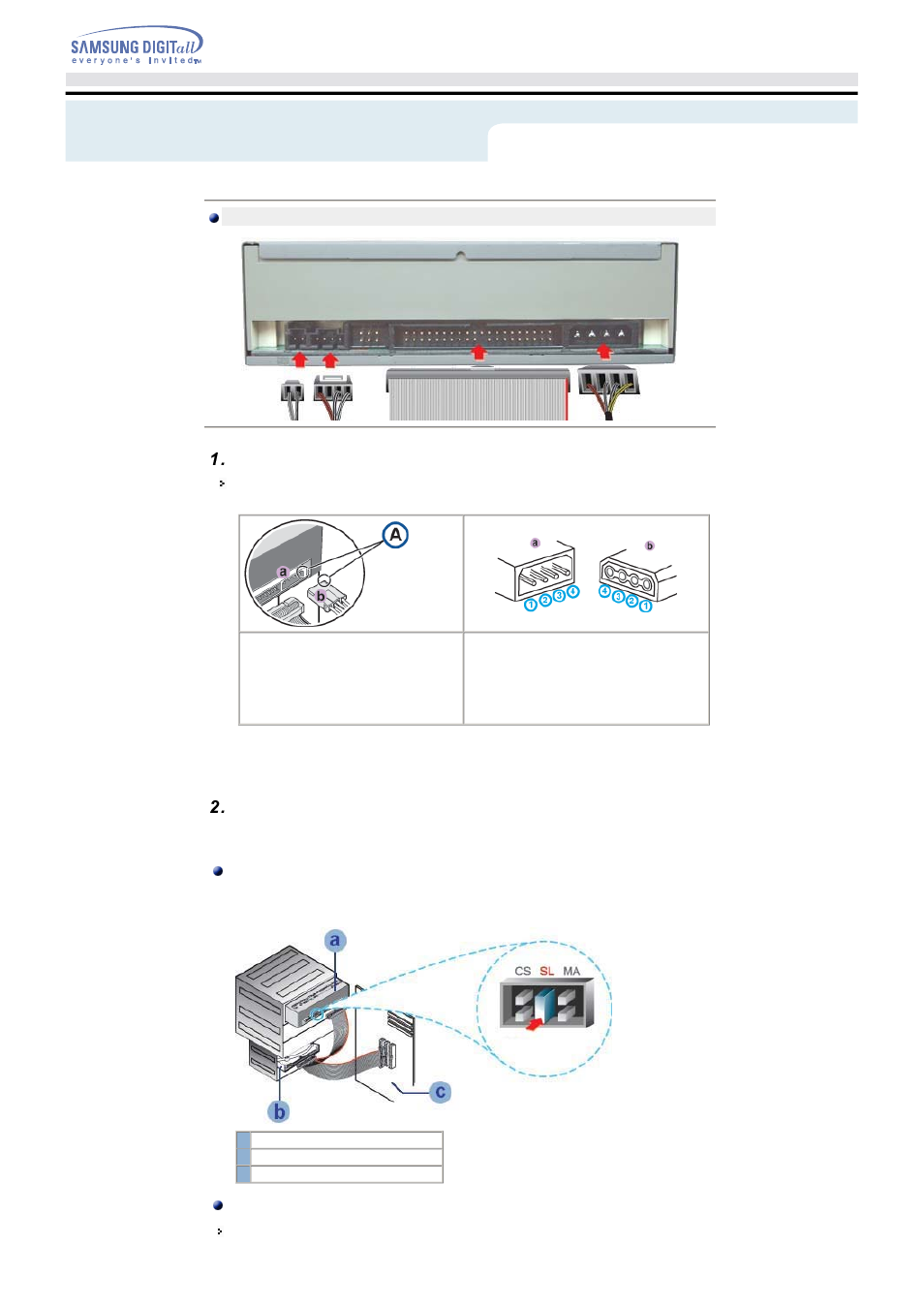
Connecting the power cable
The 4-pin power cable from the internal power unit of your computer must be connected to the power
terminal on the rear of the Optical drive drive.
A - Cut S-IDE
1 +5V DC
2 Ground
3 Ground
4 +12V DC
Note: An improperly connected power cable may cause trouble. Check the direction of the power connector
and the incline S-IDE of the Optical drive before connecting.
Connecting the E-IDE cable
Insert the E-IDE cable (40-pin), which is connected to the hard disk to the interface terminal.
(Place the red line of the cable close to the Pin 1.)
When using one E-IDE cable
Connect the cable to the SL (Slave) of the Master/Slave Select Terminal at the rear of the Optical
drive.
a : Slave Drive (Choose the SL Jumper)
b : Hard Drive
c : MainBoard
When using two E-IDE cable
If there is only one Optical drive, select MA (Master).