Assembly instructions – Allstar Products Group MVP-SB User Manual
Page 6
6
ASSEMBLY INSTRUCTIONS
STEP 6:
VERY IMPORTANT: REINSTALL
THE BELT RETAINING BLOCK REMOVED IN
STEP 1 AT THIS TIME. SEE ILLUSTRATION E.
Failure to reinstall the Belt Retaining Block may cause
the operator to not reverse correctly. Tighten the two
screws to securely hold the Belt Retaining Block in
place.
Install the Belt Guard by seating the guard over the the
Drive Sprocket and Rear Idler Pulley on the power unit
and snapping into place, see Illustration E. When
properly fitted the center round protrusion on the Drive
Sprocket fits in the hole in the rear of the Belt Guard
and the front of the Belt Guard fits over the Sensing
Plate stud. The Belt Guard should
not interfere with the belt, drive
sprocket or idler pulley in any
way. The Limit Cams are
installed at the factory.
Their settings should be
considered temporary
and may be
changed as
required during
installation.
See Page 16
“Limit Settings.
STEP 7:
Install the Rubber Bumper into its mounting hole on the Tee Rail (see Illustration E for location).
Secure the Bumper to the bottom of the Tee Rail using one 5/16-18 x 1" hex head bolt and one 5/16"-18
washered nut (supplied)
Tighten the bolt a MAXIMUM
of 1.5 additional turns after the
bolt and nut are snug.
STEP 8: Recheck
the nuts
used to secure the Tee Rail to
the Power Unit, making sure
they are tight.
Recheck
that
the Belt Retaining Block has
been reinstalled, the belt
tension is proper, there is no
belt twist, the Belt Guard is in
place, and the position of both
the Close Limit Switch and
Open Limit Switch Actuators
is appropriate to accept the
limit cams on the belt.
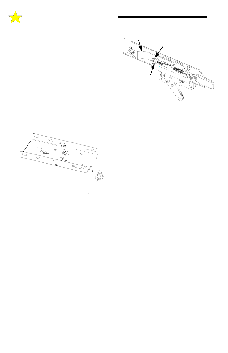
BELT
TENSION
SPOON
TIGHTEN NUT
SO APPROX.
1 INCH OF
THREADS SHOW
OUTER
NUT
Illustration D