Operating instructions, Initial checklist, Identification – Wesley PC-325-6SA User Manual
Page 12: Charging, Vehicle controls, meters, switches, Operating, Instructions
Owner’s Manual and Service Guide – PMT Series
12
OPERATING
INSTRUCTIONS
I
NITIAL
C
HECKLIST
Use the following checklist to inspect and prep your vehicle
prior to initial use.
□
Check for evidence of leaking fluids, i.e. battery acid, or
gear oil.
□
Check condition of tires and tire air pressure. Maximum
90 psi Cold; 60 psi recommended. (Pneumatic tires
only).
□
Check to ensure wheel lug nuts are tight.
□
Check for tight/corrosion free battery connections
□
Check for smooth operation of controls, switches, and
brakes.
□
Charge batteries.
□
Confirm that the brake fluid is at the proper level
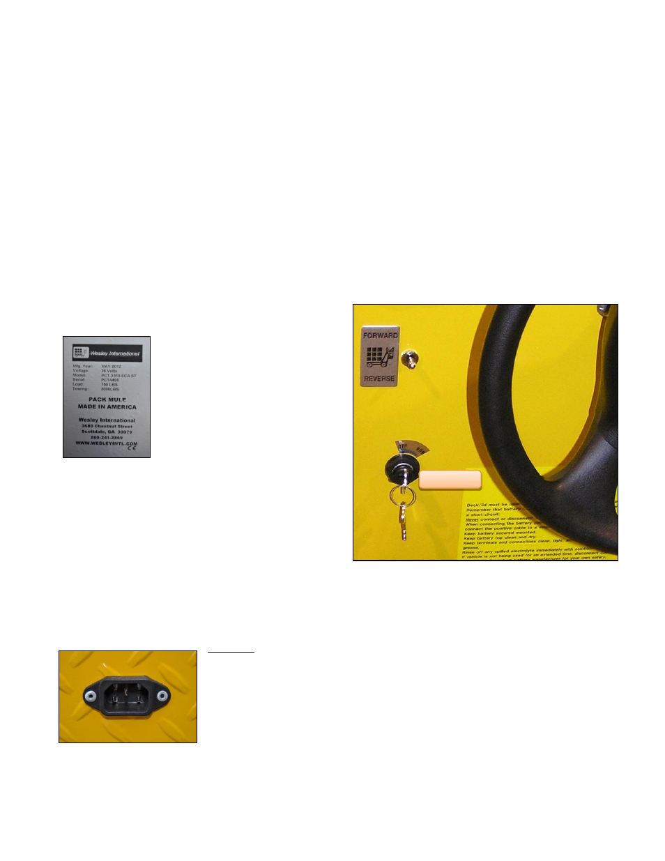
I
DENTIFICATION
The product model number, serial
number & year of manufacture is
located on a silver label ( Figure
1), either on the front of the vehicle
near
the
switches,
on
the
underside of the plate where the
seat is mounted or inside the
motor compartment attached to a
side panel.
Whenever you correspond with
Wesley
International
regarding
your
vehicle,
include
this
information.
C
HARGING
B
ATTERIES
Our Pack Mule electric vehicles come standard with an
onboard charger. They also come available with a slide out
battery system, in which case, no onboard charger is
included. If your unit comes with the onboard charger, place
the vehicle in a well-ventilated area and follow these steps to
charge the battery:
1. Position the vehicle within reach of an electrical
outlet.
2. Check all battery cells for proper acid level. Fluid
should be above plates.
3. Plug in the charger AC line cord (Figure 2) which is
already attached to the charger into a wall plug.
CAUTION:
Extension
cords must be a 3-wire
cord no longer than
30m (100’) at 10AWG
or 7.5m (25’) at 16
AWG per UL guidelines.
Only
connect
ONE
charger to a single 15A
circuit or the circuit may
become overloaded.
Figure 2
V
EHICLE
C
ONTROLS
,
M
ETERS
,
S
WITCHES
The controls, meters and switches consist of:
Key Switch, Perma-Key Switch, or On/Off Switch
FWD/REV Directional Selector Switch
Battery Discharge Indicator (BDI)
Headlight / Tail Light Switch (Optional)
Parking Brake
Speed Control Pedal
Brake Pedal
Horn Button
Foot Presence Switch (Optional)
Key Switch: For vehicles equipped with a key switch (Figure
3), the vehicle only operates when the key is in the switch. It
has two positions
– run and off.
F
IGURE
3
Perma-Key Switch (Optional): An optional Perma-Key
switch is available to replace the standard key switch. It
works the same way, but eliminates the need for a separate
key that may get lost. It has two positions
– run and off.
F
IGURE
1
Key Switch