Conductivity, Figure 7-1 presents – Campbell Scientific TDR Probes CS605, CS610, CS630, CS635, CS640, CS645 User Manual
Page 11
TDR Probes CS605, CS610, CS630, CS635, CS640, CS645
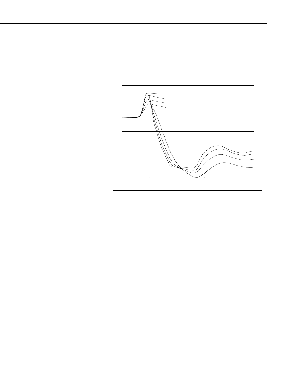
datalogger algorithm to analyze the waveform are shifted by the cable losses
resulting in error. For the data shown in FIGURE 7-1, the water content
measurement using the 66 meter cable was in error by about 1.5% volumetric
water content when electrical conductivity is low. However, in saline soils, the
error can be several percent. See Bilskie (1997) for complete results of the
study.
16 meter cable
26 meter cable
45 meter cable
66 meter cable
FIGURE 7-1. Waveforms collected in a sandy loam using CS610 probe
with RG8 connecting cable. Volumetric water content is 24% and
bulk electrical conductivity is 0.3 dS m
-1
.
In general, water content is overestimated with increasing cable length. A
calibration of volumetric water content with apparent dielectric constant for a
given cable length can improve accuracy. Measurement precision at longer
cable lengths will be maintained as long as soil electrical conductivity does not
prevent a reflection from the end of the probe rods. This is discussed later in
this section.
Minimizing cable lengths should always be considered in the design of a
measurement system using TDR. If long cable lengths are necessary, the
adverse effects can be minimized by using low attenuation cable such as RG8
or LMR-200. Careful probe design ensures correct probe impedance giving
robust reflections.
7.4 Water Content Measurement Error from Soil Electrical
Conductivity
The signal at the probe will be attenuated when ionic conduction occurs in the
soil solution. This inherent attenuation is used in TDR measurements to
determine soil electrical conductivity as described by equation [5] in the
TDR100 manual. The presence of ions in the soil solution provides a path for
electrical conduction between TDR probe rods. The attenuation of the signal
5