2 electrical parameters, 1 sdm-sio1 current consumption, Electrical parameters – Campbell Scientific SDM-SIO1 Serial Input/Output Module User Manual
Page 9: Sdm-sio1 current consumption
SDM-SIO1 Serial Input/Output Module
2.2 Electrical Parameters
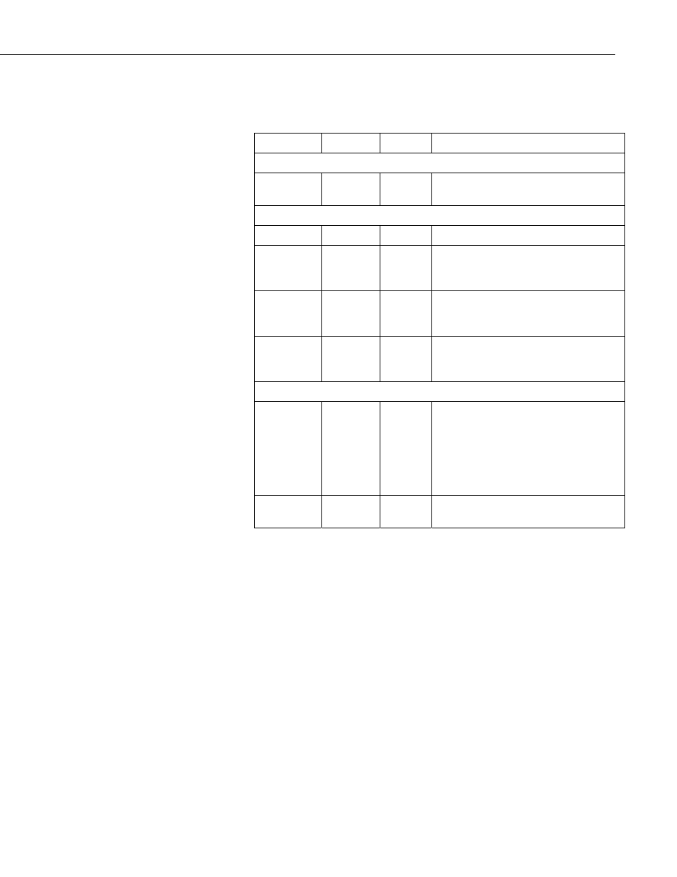
2.2.1 SDM-SIO1 Current Consumption
Nominal
Max
Notes
General Currents
Standby
current
70 µA
100 µA
Current after SerialClose has been
called.
RS-232 and RS-485 Current Consumption
(1)
Idle current
5.5 mA
6 mA
After SerialOpen has been called
Idle current
(receive
only)
4.1 mA
4.5 mA
After SerialOpen in receive only mode
Active
current (RS-
232)
11.5 mA
12 mA
Active RS-232 command
Active
current (RS-
485)
12.5 mA
13 mA
Active RS-485 command (no
termination resistors)
Line Load Currents
RS-232 line
load
2 mA per
load
3 mA
per load
Average expected increase in drawn
current per RS-232 line connected in
idle or active modes (no extra current in
stand-by mode).
Both TX and RTS are considered to be
RS-232 loads.
RS-485 line
load
(2)
40 mA
(3)
77 mA
(4)
This extra current is only present when
actively transmitting
(1) All currents are measured with no loads connected
(2) The RS-485 transmit pair is disabled when not transmitting in order to save
power higher value resistors can be used to save power dependent upon the
application. For many applications, especially with shorter cable runs, no
load/termination resistors will be needed.
(3) Single 100R load between transmit lines. Two 100R resistors (one on each
end) is the maximum recommended loading. Removing any termination
resistance should dramatically decrease current consumption during transfer of
data
(4) The RS-485 interface is protected against short circuits via a 44R resistance
making this the maximum current possible even during short circuit. This
resistance is part of the ESD protection circuitry and will be present at all
times; it shouldn’t affect normal circuit operations. The ‘RS-485 internal
circuit diagram’ in Section 3.3.4, RS-485 Internal Circuit Diagram, shows the
circuit in detail.
3