1 rs-485 one to one connection example, Rs-485 one to one connection example – Campbell Scientific SDM-SIO1 Serial Input/Output Module User Manual
Page 15
SDM-SIO1 Serial Input/Output Module
3.3 Examples for Connecting the SDM-SIO1 to Other
Equipment
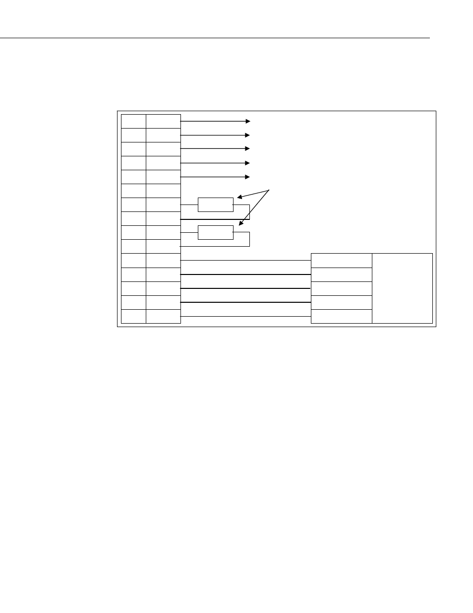
3.3.1 RS-485 One to One Connection Example
1 C1
2 C2
3 C3
To
logger
4 G
5 +12V
6 G
100
R
or
higher
7
RX-A
R
8 CTS-B
9
RTS-Y
R
10 TX-Z
11 0V
RS-485
0V
12 Z
RS-485_B
13 Y
RS-485_A
14 B
RS-485_Z
15 A
RS-485_Y
RS-485
equipment with
termination
resistors
Notes:
• Z, Y, B and A are connected to their corresponding differential wire pairs
when in RS-485/RS-422 mode. Where A and Y are the ‘+’ lines and ‘B and Z
are the ‘-‘ lines.
• Connections 7-10 are connected internally to connections 12-15. This allows
for terminations resistors to be added when in RS-485 mode (if needed) or,
more than one connection to the I/O lines or TX and RX lines in RS-232 mode.
• If the use of termination resistors is required in RS-485 mode then they
should be connected between pins TX-Z and RTS-Y for the ZY line and CTS-
B and RX-A for the A B line (see diagrams elsewhere in document).
• In half duplex RS-485/RS-422 mode the Z Y and A B pairs are connected
internally by the hardware without the need for any user interaction. The user
should connect their wires to ZX and YS, as ‘A’ and ‘B’ are disabled.
9