Sdm-cd16s 16 channel solid state dc control module, Function – Campbell Scientific SDM-CD16S 16-Channel Solid State DC Relay Controller Module User Manual
Page 5
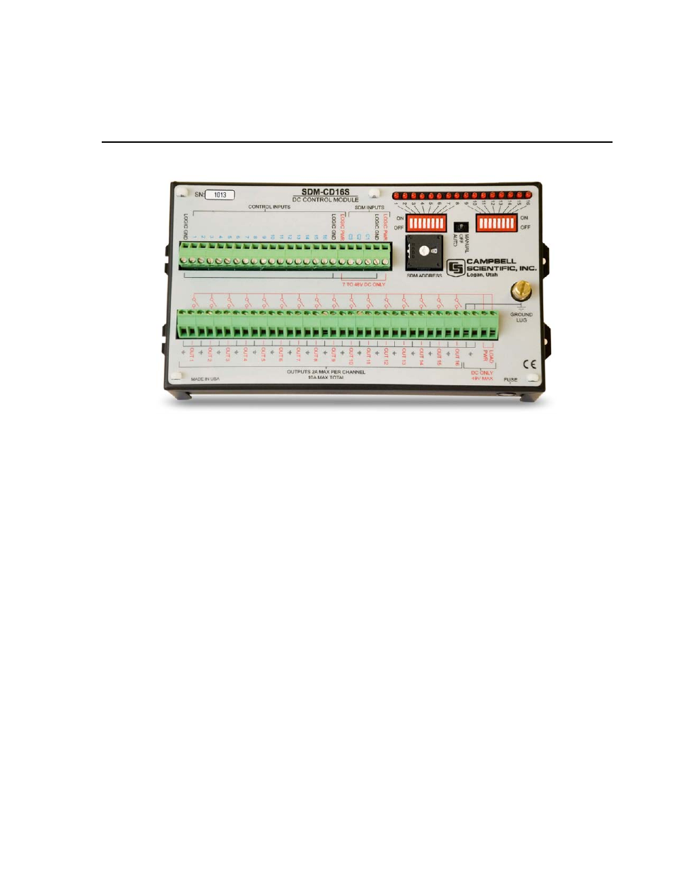
SDM-CD16S 16 Channel Solid State DC
Control Module
FIGURE 1. SDM-CD16S Face Panel
1. Function
The SDM-CD16S has 16 DC voltage outputs that can be switched on and off
manually or under datalogger control. Separate inputs for the power to the
outputs (48 VDC max) and the power to SDM-CD16 logic (7 – 48 VDC)
allow the option of powering the logic from the datalogger 12 V while
switching a higher voltage. LEDs allow a visual indicator of active outputs.
The outputs can be controlled by a datalogger or controlled manually with a
manual override toggle switch and individual rocker switches for each of the
outputs.
The toggle switch has three positions: MANUAL, OFF and AUTO. In the
MANUAL position, outputs are controlled by the position of the individual
rocker switches. In the OFF position, all outputs are off. In the AUTO
position, the state of the relays is controlled by the SDM commands from the
datalogger or by the logic control inputs.
The SDM-CD16S is a synchronously addressed datalogger peripheral.
Datalogger control ports 1, 2, and 3 are used to address the SDM-CD16S, then
clock out the desired state of each of the 16 control ports. Up to 16 SDM-
CD16Ss may be addressed, making it possible to control a maximum of 256
ports from the datalogger’s first three control ports. The SDMCD16AC
instruction is used to control the SDM-CD16S in CRBasic dataloggers. In
1