Li200s pyranometer, General, Specifications – Campbell Scientific LI200S-L LI-COR Silicon Pyranometer User Manual
Page 3: Measurement instruction
1
LI200S PYRANOMETER
1. GENERAL
This manual provides information for interfacing
a CR10, 21X, and CR7 datalogger to a LI200S
Pyranometer. An instruction manual provided
by LI-COR contains the sensor calibration
constant and serial number. Cross check this
serial number against the serial number on your
LI200S to ensure that the given calibration
constant corresponds to your sensor.
2. SPECIFICATIONS
Stability:
<
±
2% change over a 1 year
period
Response Time:
10
µ
s
Temperature
Dependence:
0.15% per
°
C maximum
Cosine Correction: Cosine corrected up to 80
°
angle of incidence
Operating
Temperature:
-40 to 65
°
C
Relative Humidity:
0 to 100%
Detector:
High stability silicon
photovoltaic detector (blue
enhanced)
Sensor Housing:
Weatherproof anodized
aluminum case with acrylic
diffuser and stainless steel
hardware
Size:
0.94” dia x 1.00” H (2.38 x
2.54 cm);
Weight:
1 oz. (28 g)
Accuracy:
Absolute error in natural
daylight is
±
5% maximum;
±
3% typical
Typical Sensitivity: 0.2 kWm
-2
mV
-1
Linearity:
Maximum deviation of 1%
up to 3000 Wm
-2
Shunt Resistor:
Adjustable, 40.2 to 100
Ω
,
factory set to give the
above sensitivity
Light Spectrum
Waveband:
400 to 1100 nm
NOTE: The black outer jacket of the cable
is Santoprene
®
rubber. This compound was
chosen for its resistance to temperature
extremes, moisture, and UV degradation.
However, this jacket will support
combustion in air. It is rated as slow
burning when tested according to U.L. 94
H.B. and will pass FMVSS302. Local fire
codes may preclude its use inside buildings.
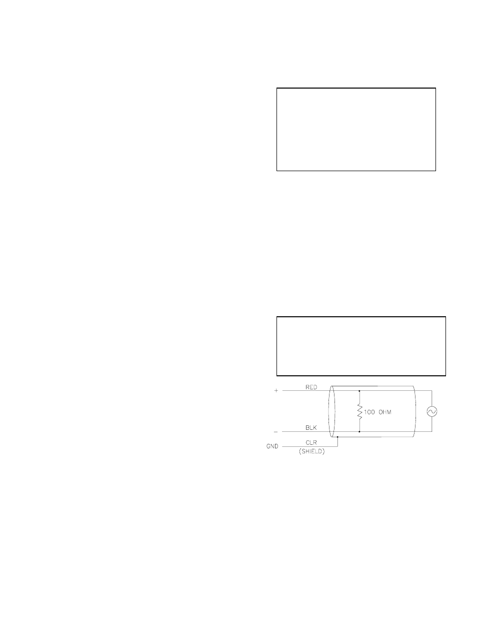
3. MEASUREMENT INSTRUCTION
The LI200S (refer to Figure 1) outputs a low
level voltage ranging from 0 to a maximum of
about 12mV depending on sensor calibration
and radiation level. A differential voltage
measurement (Instruction 2) is recommended
because it has better noise rejection than a
single-ended measurement.
If a differential channel is not available, a single-
ended measurement (Instruction 1) is a
possibility. As a test, wire the LI200S as shown in
Figure 2 and make single-ended and differential
measurements. Compare results to determine
the acceptability of a single ended measurement.
NOTE FOR 21X USERS: Slight ground
potential differences are created along the 21X
analog terminal strip when the datalogger
power supply is powering external peripherals.
If the peripherals draw about 30mA or greater,
the LI200S must be measured differentially.
Figure 1. LI200S Schematic
INPUT RANGE
An example showing how to determine the
optimum input range for a given sensor
calibration and maximum irradiance follows.
This is an example only. Your values will be
different.