Wiring, Example programs – Campbell Scientific IRTS-P Precision Infrared Temperature Sensor User Manual
Page 7
IRTS-P Precision Infrared Temperature Sensor
3
4. Wiring
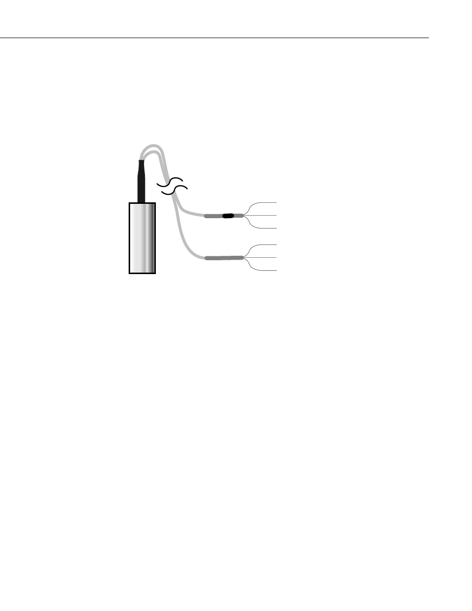
The IRTS-P has two thermocouple outputs. Each output is a pair of red and
yellow wires. The pair labeled “Target” on the jacket near the wires is the
output from the detector. The pair labeled “Body” is a thermocouple
measuring the temperature of the sensor body. Previous versions of the sensor
had a black band on the target cable to mark it. We recommend measuring the
temperatures with differential voltage thermocouple measurements.
5. Example Programs
The datalogger program to measure the IRTS-P measures the thermocouple
outputs to obtain the IRTS-P sensor body temperature and the apparent
(uncorrected) temperature of the target.
The thermocouple temperature requires the temperature of the terminals to
which the thermocouples are connected. The panel temperature is used as the
reference for the CR23X, CR1000, and CR5000. The module temperature is
not an accurate measurement of the CR10X panel temperature; a CR10XTCR
is required to measure the reference temperature.
After measuring the thermocouple outputs, the sensor body temperature is used
to calculate correction coefficients that are then used to correct the target
temperature.
All three example programs measure the sensor once a second and output
average values once an hour. The actual channels and outputs intervals need to
be adjusted for the actual installation and application.
The equations implemented in the program are (Bugbee
et.al. 1996)
Corrected Target Temperature,
SEC
ATT
CTT
−
=
were
ATT
= Apparent Target Temperature,
and Sensor Error Correction,
)
)
)((
/
25
.
0
(
2
SB
SB
SB
K
H
ATT
P
SEC
−
−
=
;
Target – Detector Temperature:
Yellow TC + Differential High
Red TC –
Differential Low
Bare -
Ground
Sensor Body Temperature:
Yellow TC +
Differential High
Red TC –
Differential Low
Bare -
Ground
Body
Target