Measurement concepts, 1. curs100, Schematic – Campbell Scientific CURS100 100 Ohm Current Shunt Terminal Input Module User Manual
Page 8
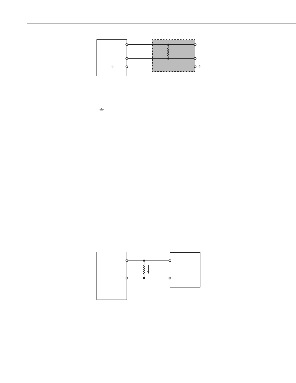
CURS100 100 Ohm Current Shunt Terminal Input Module
Datalogger
Rshunt
100 Ω
± 0.01%
H
L
or G
or AG
H
L
CURS100
FIGURE 2-1. CURS100 schematic
The CURS100 has three pins: high, low, and ground; these pins are the correct
spacing to insert directly into the datalogger’s high, low, and ground terminals
(
on 21X, CR23X, CR800, CR850, CR1000, CR3000, CR5000, or
CR9000(X) or AG on CR10(X)).
3. Measurement Concepts
Transducers that have current as an output signal consist of three parts: a
sensor, a current transducer (quite often integrated with the sensor), and a
power supply. The power supply provides the required power to the sensor and
the transducer. The sensor signal changes with the phenomenon being
measured. The current transducer converts the sensor signal into a current
signal. The current output changes in a known way with the phenomenon
being measured.
An advantage of current loop transducers over voltage output transducers is the
current signal remains constant over long lead lengths.
Two disadvantages with current loop transducers are as follows. First, most
transducers require constant current from the power supply, adding cost and
size. Secondly, the conditioned output quality may not be as good as a similar
unconditioned sensor being measured directly by a datalogger.
The output of the transducer is wired so the current must flow through the 100
ohm resistor in the CURS100.
Datalogger
Transducer
H
L
Signal
Signal Return
I
Ohm’s law describes how a voltage (V) is generated by the signal current (I)
through a completion resistor (R):
V = I (R).
This voltage is measured by the datalogger.
2