Transducer wiring, 1 two-wire transducers, Two-wire transducers – Campbell Scientific CURS100 100 Ohm Current Shunt Terminal Input Module User Manual
Page 10: A jumper wire
CURS100 100 Ohm Current Shunt Terminal Input Module
Signal From Sensor
Sensor Cable Shield
Sensor Power
Jumper
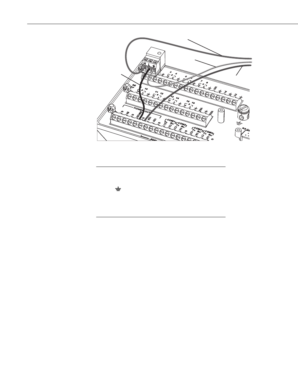
FIGURE 3-1. CURS100 L terminal connected to a datalogger G
terminal using a jumper wire.
Normally the L terminal on the CURS100 should be connected
to a datalogger G terminal (power ground) with a jumper wire
(FIGURE 3-1). Connecting the L terminal to the adjacent
ground (
or G) terminal on the CURS100 can result in
unwanted return currents on the datalogger signal ground, which
could induce undesirable offset errors in low-level, single-ended
measurements. The G terminal on the CURS100 can be used to
connect cable shields to ground.
NOTE
4. Transducer Wiring
Current transducers differ mainly in how they are powered and in the relative
isolation of the current output. In this section, the transducers are grouped by
the total number of wires the transducer uses to obtain power and output the
current.
4.1 Two-Wire Transducers
In a two-wire transducer, the power supply is in series within the current loop.
The transducer regulates the amount of current that flows; the current drawn
from the battery is exactly the current used as a signal.
4