3 programming and sensor hook-up – Campbell Scientific AVW1 and AVW4 Interfaces for Vibrating Wire Sensors User Manual
Page 12
AVW1/AVW4
2-6
2.3 PROGRAMMING AND SENSOR HOOK-UP
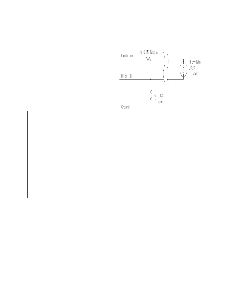
Measure the thermistor with Instruction 4 using
a measurement range of 2500 mV fast, an
excitation voltage of 2500 mV, a delay of 1, and
a multiplier of 0.001. The resulting value is
linearized with Instruction 55 using the following
coefficients: C0 = -104.78, C1 = 378.11, C2 = -
611.59, C3 = 544.27, C4 = -240.91, C5 =
43.089. The output is in degrees Celsius and
covers the range from -5
o
C to +60
o
C. Due to
the small current requirement, up to 118
thermistors could theoretically be powered by
one excitation channel.
When measuring the Geokon temperature
through CSI's AVW1 or AVW4, see Sections 4
or 5 respectively for hook up information.
NOTE:
This manual covers AVW1's with
serial number 1093 and up plus serial
numbers 1002, 1034, 1040A, 1041, 1042,
1051, 1052, 1055, 1057, 1058, 1059, 1069,
1071, 1073, 1076, 1080, 1084, 1086, 1087,
1088, 1088A, 1089A, 1090A, 1091A, and
1092A. This manual also covers AVW4s
with serial number 1045 and up plus serial
numbers 1034 and 1038. These serial
numbers mark a change in circuitry that
changes the excitation voltage for the
temperature measurement from -2500 mV
(before) to +2500 mV (after). The multiplier
also changed from -.001 (before) to +.001
(after). The values of the resistors in
locations B4 and C4 for the AVW1 and
locations D4 and E4 for the AVW4 were
changed to the values shown in the current
schematics.
When measuring the Geokon temperature
directly with the CR10, connect the leads and
bridge completion resistors as shown in Figure
2.3-1.
FIGURE 2.3-1. Direct Measurement of the
Geokon Thermistor