Operation, 1 siting, 2 wiring – Campbell Scientific A100LK Anemometer User Manual
Page 13
A100LK Anemometer
7. Operation
7.1 Siting
Locate wind sensors away from obstructions (e.g., trees and building). As a
general rule, there should be a horizontal distance of at least ten times the
height of the obstruction between the anemometer and the obstruction. If
mounting the sensors on the roof of a building, the height of the sensors, above
the roof, should be at least 1.5 times the height of the building. See Section 10,
References for a list of references that discuss siting wind speed and direction
sensors. For power performance applications refer to IEC 61400-12-1 which
specifies the mounting and location of anemometers.
7.2 Wiring
When Short Cut for Windows software is used to create the datalogger
program, the sensor should be wired to the channels shown on the wiring
diagram created by Short Cut.
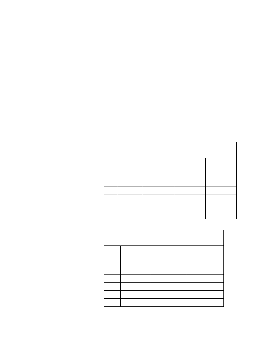
Tables 7-1 and 7-2 show the connections to Campbell Scientific dataloggers.
TABLE 7-1. Connections to Campbell Scientific Dataloggers
Pulse Channels
Color
Wire Label
CR800
CR850
CR5000
CR3000
CR1000
CR510
CR500
CR10X
21X
CR7
CR23X
White Signal Pulse
Pulse
Pulse
Red 12V
12V
12V
12V
Blue Ground
G
G
G
Clear Shield
Analog
Ground Analog Ground Analog Ground
TABLE 7-2. Connections to Campbell Scientific Dataloggers
Control Ports
Color
Wire Label
CR800
CR850
CR5000
CR3000
CR1000
CR10X
White Signal
C1-C8
C6-C8
Red 12V
12V
12V
Blue Ground
G
G
Clear Shield
Analog
Ground Analog
Ground
7