Battery to inverter cable connection – Samlex America SK User Manual
Page 20
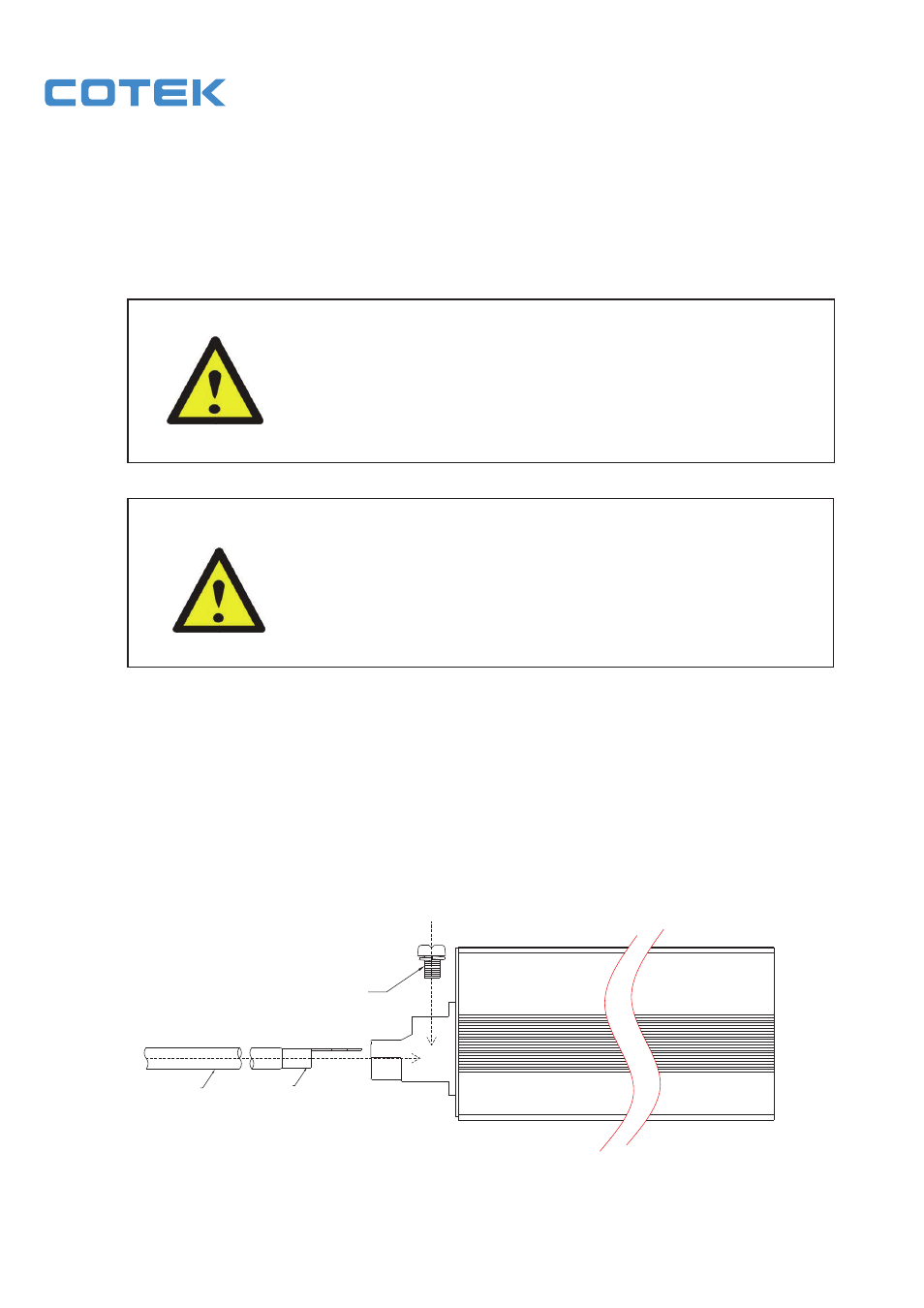
3-5-1. Connect the cables to the power input terminals on the rear panel of
the inverter. The red terminal is represents positive (+) and black
terminal represents negative (-). Insert the cables into the terminals
and tighten the screw to clamp the wires securely.
Also, use only high quality copper wire and keep cable length short, a
maximum of 3 - 6 feet.
WARNING!
The installation of a fuse must be on a positive cable.
Failure to place a fuse on “+” cables running between
the inverter and battery may cause damage to the
inverter and will void warranty.
WARNING!
Ensure all the DC connections are tight (torque
to 9 – 10 ft-lbs, 11.7 – 13 Nm). Loose connections
may cause overheat and fire.
Battery to inverter cable connection
Do not place anything between
battery cable lug and terminal surface.
Assemble exactly as shown.
18
M8 SCREW
RING TERMINAL
PVC WIRE
AWG#2-#6
- SEC-1212 (16 pages)
- SEC-1223BBM (24 pages)
- SEC-1235 (16 pages)
- SEC-1212CE (12 pages)
- SEC-1223BBM-230 (24 pages)
- SEC-40BRM (24 pages)
- SEC-2430BRM (24 pages)
- SEC-4825BRM (36 pages)
- SEC-40BRM-220 (24 pages)
- SAM-1000-12 (32 pages)
- SAM-450-12E (16 pages)
- SAM-RC (8 pages)
- SAM-1500C-12 (32 pages)
- PST-300-12 (44 pages)
- PST-120-12 (12 pages)
- PST-600-12 (48 pages)
- PST-1500-12 (48 pages)
- RC-15A (8 pages)
- RC-200 (8 pages)
- PST-15S-12A (32 pages)
- PST-15S-12E (48 pages)
- PST-60S-12E (48 pages)
- SA-150 (15 pages)
- SA-600R (20 pages)
- SA-1000K (23 pages)
- SA-1500 (34 pages)
- SA-2000K (21 pages)
- SK (25 pages)
- SK120 (20 pages)
- S600 (24 pages)
- S1500 (39 pages)
- PSE-12125A (36 pages)
- PSE-24125A (36 pages)
- TN-1500 (20 pages)
- ST1000-112 (26 pages)
- ST1500-124 (40 pages)
- SR1000-124 (37 pages)
- BP-1210 (11 pages)
- BW-01 (2 pages)
- BATTERY MONITOR BW-03 (4 pages)
- SC-05 (12 pages)
- BBM-1225 (12 pages)
- BBM-12100 (12 pages)
- IDC-100 (4 pages)