Samlex america inc. | 5 led display, Pinout of rj-50 modular jack, The following led displays are available – Samlex America RC-200 User Manual
Page 5
SAMLEX AMERICA INC. | 5
LED Display
The following LeD displays are available:
•
Green LeD (6) marked PoWeR. This LeD will be lighted when the inverter is in oN
condition. When the inverter is in off condition, this LeD will not be lighted. This
LeD shows that DC input is available to the inverter and that the input section of the
inverter is operating normally
•
Red LeD (4) marked oVeR LoAD. When lighted, it indicates that the AC output of the
inverter has been shut down due to over load
•
Red LeD (5) marked oVeR TeMP. When lighted, it indicates that the AC output of the
inverter has been shut down due to over temperature
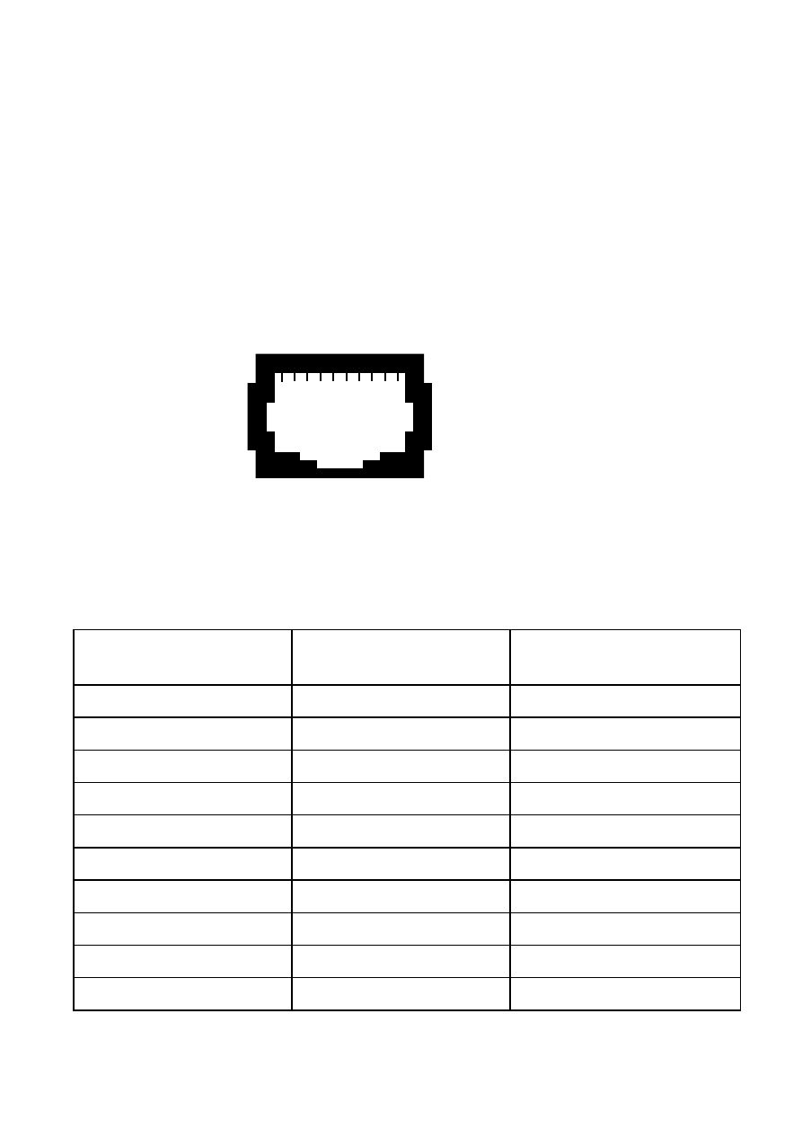
Pinout of Rj-50 Modular jack
The pinout of the RJ-50 Modular Jack (7) at the back of the unit is given at fig.
2 below:
Fig. 2 Remote Control RC-200 - Pinout of Modular Jack RJ-50
The standard numbering system of the pins of a Modular Jack, when looking into
the Jack, is from left to right. As the conductors of the cable are cross-connected
(rolled-over), the pinouts at the Modular Jack in the inverter will be a mirror image
of the pinout of the Modular Jack in the Remote Control as shown in table below:
Pinout of Modular jack on
the Remote Control
1
Signal
Pinout of Modular
jack on the inverter
2
1
Toggle
10
2
Avcc
9
3
Ground for LeDs
8
4
Vcc
7
5
LeD - “PoWeR oN”
6
6
LeD - “oVeR TeMP”
5
7
LeD - “oVeR LoAD”
4
8
LCD - Light
3
9
LCD - Data
2
10
LCD - Ground
1
1 2 3 4 5 6 7 8 9 10
LEGEND
Toggle
Avcc
Ground for LEDs
Vcc
LED - “Power ON”
LED - “Over Temp”
LED - “Over Load”
LCD - Light
LCD - Data
LCD - Ground
1.
2.
3.
4.
5.
6.
7.
8.
9.
10.
Figure 2 Remote Control RC-200; Pintout of Modular Jack RJ-50
1. As shown in Figure 2
2. Mirror image of Remote Control Jack due to crossed-over /rolled over connection of conductors.