Principle of operation - inverter – Samlex America SAM-1500C-12 User Manual
Page 7
4 | SAMLEX AMERICA INC.
SAMLEX AMERICA INC. | 5
SECTION 2 |
Features, Applications &
Principle of Operation
SECTION 2 |
Features, Applications &
Principle of Operation
principle of operation - inverter
Conversion of 12 VDC from the battery / other DC source to 115 VAC takes place in 2
stages. In the first stage, the 12 VDC is converted to high voltage DC (around 160 VDC)
using high frequency switching and Pulse Width Modulation (PWM) technique. In the
2nd stage, the 160V high voltage DC is converted to 115V, 60 Hz Modified Sine Wave AC.
(note: 115V is the RMS value of the Modified Sine Wave AC voltage. The peak value of
the Modified Sine Wave AC voltage will be equal to the value of the above high voltage
of around 160V. See the fig 2.1 below).
moDifieD Sine WaVeform - cHaracteriSticS
& compariSon WitH pure Sine WaVeform
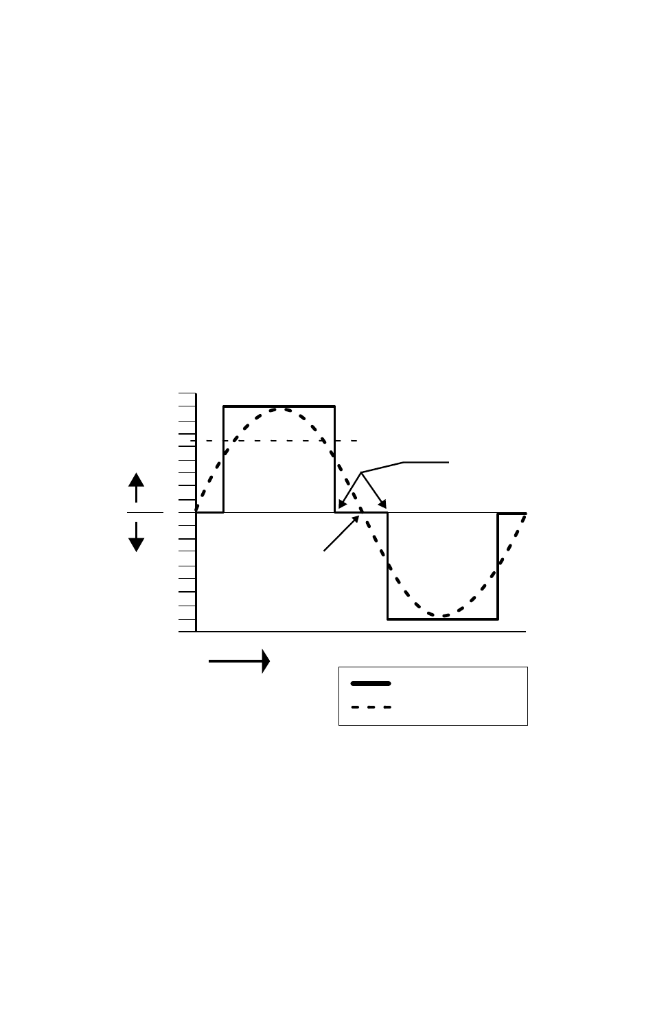
Please refer to Fig 2.1 below which shows one cycle of Modified Sine Wave and Pure Sine
Wave for comparison.
Fig 2.1 Modified Sine Wave and Pure Sine Wave - Comparison
The output waveform of the inverter is a Modified Sine Wave. In a Modified Sine Wave,
the voltage waveform consists of rectangular pulses that approximate sine wave pulses
of a Pure Sine Wave. The voltage rises and falls abruptly at a particular phase angle and
sits at 0 Volts for some time before changing its polarity. In a Pure Sine Wave, the voltage
rises and falls smoothly with respect to phase angle and the voltage changes its polarity
instantly when it crosses 0 Volts.
TIME
180
160
140
120
100
80
60
40
20
0
20
40
60
80
100
120
140
160
180
Modified Sine
Wave sits at
0V for some
time and then
rises or falls
Sine Wave
Modified Sine Wave
Pure Sine Wave
crosses 0V
instantaneously
Legend
V +
V -
115 RMS