Table 5.1: inverter sizing factor, Switching on/off inverter, Switching on /off battery charger – Samlex America SAM-1500C-12 User Manual
Page 21
18 | SAMLEX AMERICA INC.
SAMLEX AMERICA INC. | 19
Sizing chart for typical Loads that require High Starting Surge
The manufacturers’ specifications for power rating of appliances and devices indicate
only the Running Power required. The Surge Power required by some specific types of
devices as explained above has to be determined by actual testing or by checking with
the manufacturer. This may not be possible in all cases and hence, can be guessed at
best, based on some general rules of Thumb.
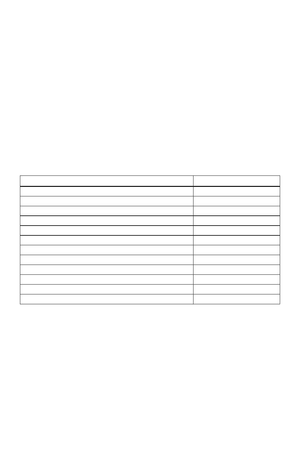
Table 5.1 lists some common loads that require high surge power on start up. A “Siz-
ing factor” has been recommended against each which is a Multiplication factor to be
applied to the rated running Watt rating of the load to arrive at the Continuous Power
rating of the inverter (multiply the running Watts of the device/ appliance by the Sizing
factor to arrive at the size of the inverter).
taBLe 5.1: inVerter SiZinG factor
type of Device or appliance
inverter Sizing factor
1
Air Conditioner / Refrigerator / Freezer (Compressor based)
5
Air Compressor
4
Sump Pump / Well Pump / Submersible Pump
3
Dishwasher / Clothes Washer
3
Microwave (where rated output power is the cooking power)
2
Furnace Fan
3
Industrial Motor
3
Portable Kerosene / Diesel Fuel Heater
3
Circular Saw / Bench Grinder
3
Incandescent / Halogen / Quartz Lamps
3
Laser Printer / Other Devices using Quartz Lamps for heating
4
Photographic Strobe / Flash Lights2
4
noteS for taBLe 5.1
1. Multiply the running Active Power rating {Watts} of the appliance by this factor to arrive
at the Continuous Power rating of the inverter for powering this appliance.
2. For Photographic Strobe / Flash Unit, the surge power of the inverter should be > 4 times
the Watt Sec rating of photographic strobe / flash unit
Switching on/off inverter
The Inverter is switched oN/off using Inverter oN / off Switch (3, fig 3.1).
When the Inverter is switched oN, Green LeD “Inverter” (8, fig 3.1) is lighted.
Switching on /off Battery charger
The Charger is switched oN/off using Charger oN / off Switch (2, fig 3.1).
SECTION 5 |
Operation