Grounding arrangement, Caution – Samlex America SAM-1500C-12 User Manual
Page 13
10 | SAMLEX AMERICA INC.
SAMLEX AMERICA INC. | 11
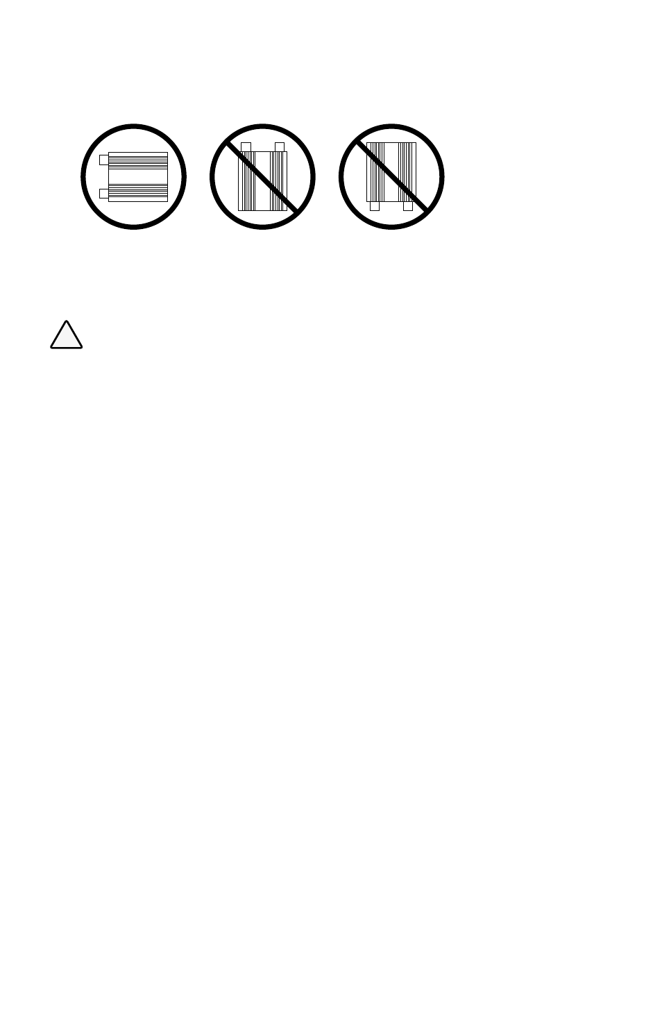
(a)
(c)
(b)
Fig 4.1
Mounting Orientation
on Wall
SECTION 4 |
Installation
Grounding arrangement
!
caution!
1. For grounding requirements, the METAL CHASSIS of the unit is connected as follows:
• To the Grounding Nut and Bolt (15, Fig, 3.1) for external Earth Ground connection,
when required.
• To the Grounding Pin of NEMA5-15P plug of the AC Input Power Cord (10A, B- Fig 3.1). When
the AC Input Power Cord is plugged into 15A/20A GfCI protected outlet being fed with Utility
AC Power, the metal chassis of the inverter automatically gets bonded to the earth Ground of
the Utility Distribution System.
• To the Grounding Terminal of the 2 x NEMA5-15R outlet(s) (1, Fig 3.2) through internal
Normally Closed (NC) Contact of relay r2.
2. following conditions will be applicable when the unit is used as a backup AC Power Source
and is connected to the Utility AC Power through AC Input Power Cord (10A, b – fig 3.1):
• utility ac power is available: The metal chassis of the unit gets bonded to earth Ground of
the Utility Distribution System. Internal Relay R2 will energize and will disconnect the
Grounding Terminals of the AC outlets from the metal chassis of the unit. IN THIS CASe, THe
MeTAL CHASSIS of THe CoNNeCTeD AC LoADS WILL be fLoATING. PLeASe eNSUre THAT
WHeN USING THe UNIT AS bACKUP AC PoWer SoUrCe, THe UTILITY AC INPUT IS feD froM
15A/20A GfCI ProTeCTeD oUTLeT To ProVIDe GroUND fAULT ProTeCTIoN.
• utility ac power is not available: The metal chassis of the unit is connected to earth Ground
of the Utility Distribution System. Relay R2 is de-energized and the metal chassis of the unit
gets connected to the Grounding Terminals of the two NeMA5-15r outlet(s). Thus, the metal
chassis of the loads also gets bonded to the earth Ground of the Utility Distribution System.
• Grounding using Grounding nut and Bolt (15, fig, 3.1): Do NoT GroUND USING THIS NUT
AND boLT. THe UNIT GeTS GroUNDeD To THe eArTH GroUND of THe UTILITY GroUNDING
SYSTeM AUToMATICALLY THroUGH THe GroUNDING WIre of THe AC INPUT PoWer CorD
(10A, b- fig 3.1). USe of MULTIPLe GroUNDS IS NoT DeSIrAbLe.
3. When the unit is being used as a stand-alone inverter (Utility AC Power input is not con-
nected), Relay R2 remains de-energized and the metal chassis of the unit remains connected
to the Grounding Terminals of the two NeMA5-15r outlet(s). in this application, connect the
Grounding nut and Bolt (15, fig, 3.1) to earth Ground using at least aWG #8 wire.
4. following operating conditions will be applicable when the unit is being used as (i) A Stand-
alone Inverter (Utility AC Power input is NoT connected) or (ii) as a backup AC Power Source
when Utility AC Power is off:
• The Line and Neutral Terminals of the NEMA5-15R AC outlets will be isolated from its
Grounding terminal. thus, the metal chassis of the ac loads and the metal chassis of the
inverter will also be isolated from the Line and neutral of the nema5-15r ac outlets.