Matrix Orbital LCD/VFD Legacy User Manual
Page 11
The RS-232 connector on the PC cable is wired so that a standard ’straight through’ 9 pin D-sub cable
may be used to connect the modules to a standard serial port such as COM ports on PCs.
Note that this
device complies with the EIA232 standard in that it uses signal levels from +/-12V to +/- 12V. To use
standard RS-232 no modifications are required. The display does not allow the use of TTL.
Table 4: RS-232 Pinout
Pin Number
Direction
Description LCD Host
2
From LCD module
Data out
Tx
Rx
3
To LCD module
Data in
Rx
Tx
4
-
Ground
gnd
gnd
2.1.6 I
2
C Communications
The display I
2
C communications runs at 100Kbps and supports up to 127 units on a single communica-
tions line. The I
2
C data line operates on 5 volt CMOS levels
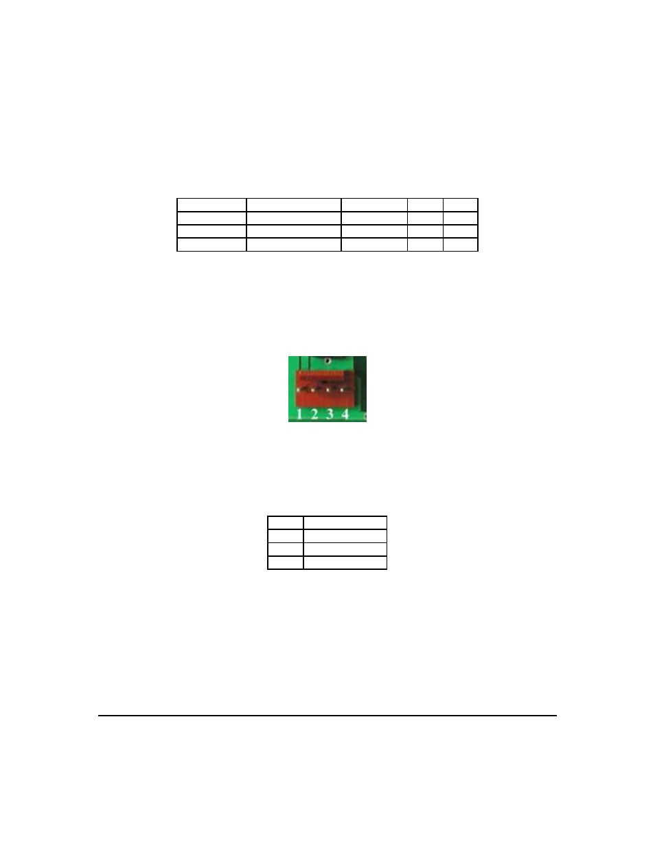
Figure 11: Power Connector
Table 5: Connector Pinout
Pin 4
Ground
Pin 3
SDA (I
2
C data)
Pin 2
SCL (I
2
C clock)
Pin 1
Vdc
2.1.7 ACK
The idea of ACK is to indicate when the data has been received correctly. ACK does not indicate data
incorrectly received. ACK simply fails to indicate when data is correctly received. Clearly, this is of limited
usefulness and even less so with Matrix Orbital modules. Matrix orbital modules are not capable of failing
to acknowledge an incorrectly received byte in response to that bytes transition. They are only capable of
failing to acknowledge the bytes following the byte, which was not received. To fully understand the reasons
Matrix Orbital
LCD4041
8