1 general, 2 connections – Matrix Orbital VK162-12 Legacy User Manual
Page 21
4.1 General
The display keypad interface processes the keypad row / column matrix into a serial (RS-232 or I
2
C)
data byte stream. Aside from this processing, the keypad has no effect on the display. To send keystrokes
to the display, they must be routed through the controller. Whenever a columns and a row pin are shorted
together, a keystroke will be generated and either held in the buffer (I
2
C) or send over the serial line to the
host (RS-232). The keypad shares the same pins as the seven GPOs on the display and only one or the other
can be used at one time.
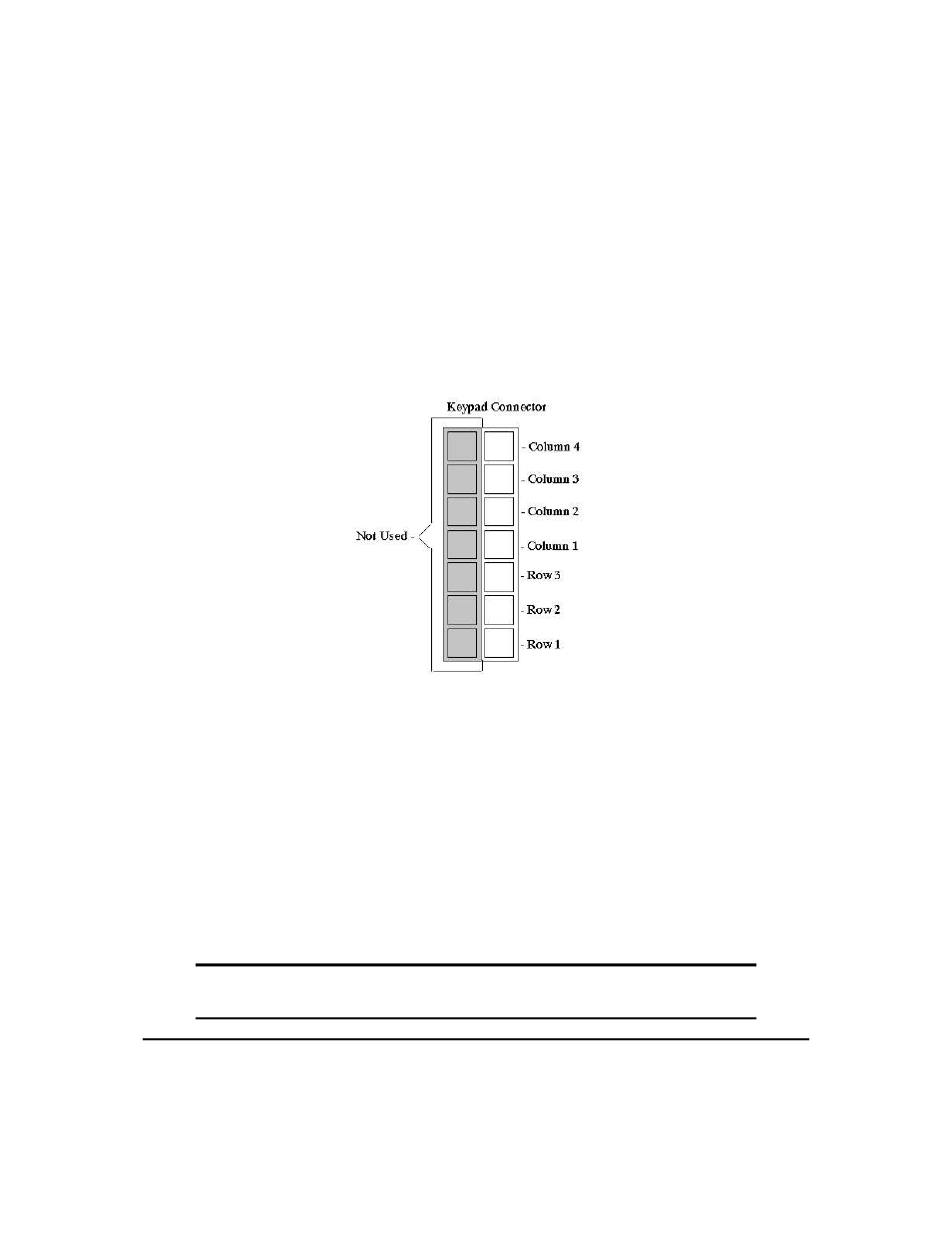
4.2 Connections
Figure 19: Keypad Connector
The connector is not ’keyed’ so the keypad will probably plug in either of two ways. The display will not
be damaged by reversing the connector, but the keypad will generate a different ASCII character mapping
for each position. If the connector has fewer than 7 pins it should be centered on the display connector,
starting with Row 3 and Column 1 and going out. Any matrix style keypad will work with the display, as
well as momentary switches.
The diagram shows the logical layout (row 1, column 1 in upper left). The connector for the keypad is a
10 pin 0.1" spacing male header. Pins 1 through 5 are columns and pins 6 through 10 are rows. The keypad
is scanned whenever a key is pressed: there is no continuous key scan. This means that key presses are dealt
with immediately without any appreciable latency. This also prevents electrical noise which is often caused
by continuous key scans.
NOTE The keypads may be laid out in a different pattern. If this is the case, the user will
need to interpret the key codes differently.
Matrix Orbital
VK162-12
17