4 setup for testing – Matrix Orbital LK202-25 Legacy User Manual
Page 6
control any aspect of the operation of the display, it acts simply as a matrix to serial converter. To use the
keypad to control the display, the controller must be programmed accordingly.
1.4 Setup for Testing
Before setting up the application the user may want to try out the display. This is easily done with a PC.
If not equipped with a dual bay PC mounting kit, the following will be required;
• A 4-pin power connector of the type used to connect 3.5" floppy drive. Take care not to connect the
display to an unmodified spare power connector in a PC
• A 5V power supply
• A PC with a spare RS-232 port (COM1 or COM2)
• A 9 or 25 pin RS-232 serial cable. If using a 25 conductor cable, a 9 to 25 pin adapter will be required
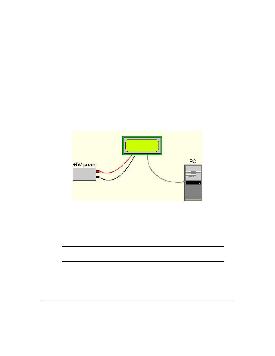
Figure 1: Connections for Testing
1. Refer to the Figure above for the following steps.
2. Wire the connector to the power supply. On most connectors the RED lead will go to +5V and the
BLACK lead to GND.
NOTE The Manufacturer’s Warranty becomes void if the unit is subjected to over-voltage
or reversed polarity.
3. Connect the display to the PC using the serial cable and adapter if required. Ensure the RS-232 cable
includes the required ground lead. There must be no voltage differential between the RS-232 ground
and the power supply ground.
4. Connect the power connector, making certain the +5V goes to V+. Turn on the power; the display
should come on.
Matrix Orbital
LK202-25
2