Installation, Figure 6: front panel adjustment, Page 11 – Clary SP U-MPL User Manual
Page 11: F(60
Page 11
CIRCUIT BREAKER
POWER
SYSTEM
COLD
LOAD
OVERRIDE
INPUT
AC4
AC3
AC2
AC1
DC3
DC1/2
ON
TEST
REPLACE
ON/OFF
SILENCE
START
FAULT
BYPASS
FULL
AC
OVER
100%
AC6
AC5
DC1/2
FAIL
FAN
OFF
HOT
WARM
TEMPERATURE
INV
ON
BATT
OK
DC3
25%
LOW
50%
75%
OUTPUT
BATTERY
STATUS
INSTALLATION
This Rackmount system is designed for installation in a protected environment. This system may
be installed in a 19" rack system. Some important points to consider when positioning a unit for
operation:
• A 20A (preferably dedicated) outlet is accessible for the power connection to the unit. It
is not recommended to modify the power cord in any way nor should an extension cord
of any kind be used. Never use a surge protected device on the output of this
system.
• The cord paths in the system installation should remain clear of foot traffic or anything
else that may disturb permanent connection.
• The installation site should maintain an ambient air temperature of less than 140
o
F
(60
o
C). When the environment for the system remains cooler during operation, there is
less stress on the batteries and the internal electronics.
• The air inlets, vents and fan should not be obstructed or blocked in any way. The more
breathing space the system has, the cooler it operates.
• The air should remain free from excessive dust and chemical fumes.
• The front panel is designed to fit in a standard 19" rack. This panel fills a 5.25
inch (3U)
slot. Guide Rails or slides are recommended to support the unit's mainframe. This
system can weigh in access of 40 pounds, therefor front panel mounting is not intended
to support the entire unit. The system comes with pre-tapped aluminum slide bars to
accept Jonathan QD-145 slides. Separate shims are included for correct slide bar
spacing if the unit is installed in a DTC-2 (C3) rack.
Once a location has been selected and the unit is installed, it is ready for operation.
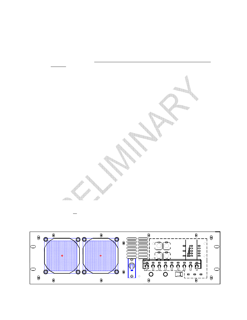
Once the unit is installed into a rack, small adjustments may be required for the front panel to
screw mount into the frame. Refer to the following steps and diagram to adjust the panel to the
desired position:
1) Loosen, but do not remove, all screws holding in the front panel.
2) Loosen, but do not remove, the four acorn nuts on the handles.
3) The entire front panel should now have limited play for exact positioning.
4) Install the four panel mounting screws in front panel slots into the rack enclosure.
5) Retighten all screws and nuts that you have loosened.
FIGURE 6: FRONT PANEL ADJUSTMENT