Waterloo F1880 User Manual
Page 2
Hardware Included:
TOOLS REQUIRED:
1/2” wrench
3/8” wrench
5/16” drill bit
7/16” wrench
Phillips Screwdriver
Cabinet:
Literature
Hardware bag
Caster pack
CASTER INSTALLATION
SIDE HANDLE ATTACHMENT
Items Needed:
#14 - 10 x 3/4" Phillips Screws (Qty: 4)
Phillips Screwdriver
Chest:
Literature
Hardware bag
• Attach the side handle using (4) #14-10x 3/4 Phillips
screws.
NOTE: There are 2 styles of caster mounting depend-
ing on the cabinet purchased. Choose the style that
applies to your cabinet.
NOTE: Not all assembly instructions will apply to your model.
WARNING
Remove wooden work surface or rubber mat, if any,
before attaching chest(s) to the cabinet.
1/4 - 20 Nut (Qty: 16)
1/4 - 20 x 5/8 Screw
(Qty: 16)
5/16 - 18 x 3/4 Screw (Qty: 16)
5/16 - 18 Nut (Qty: 16)
Process:
• Remove bottom drawers. (See Operation Section, Part
B.)
• Lay the cabinet on its back. Use packaging material to
protect the finish.
• Mount both swivel casters on the same side of the unit
as the side handle.
• Attach the casters using (4) 1/4 - 20 x 5/8" screws and
(4) 1/4 - 20 nuts per caster.
• Wrench tighten all screws. It is recommended not to
exceed 80 inch pounds of torque.
• Return the unit to its upright position.
• Reinstall bottom drawers.
Items Needed for 5 x 2 Casters:
1/4 - 20 x 5/8" Screw (Qty: 16)
1/4 - 20 Nut (Qty: 16)
7/16-in Wrench
3/8-in Wrench
Items Needed for 6 x 2 Casters:
5/16 - 18 x 3/4" (Qty: 16) 5/16 - 18 Nut (Qty: 16)
1/2-in Wrench
Process:
• Remove bottom drawers. (See Operation Section, Part
B.)
• Lay the cabinet on its back. Use packaging material to
protect the finish.
• Mount both swivel casters on the same side of the unit
as the side handle.
• Attach the casters using (4) 5/16 - 18 x 3/4" screws and
(4) 5/16 - 18 nuts per caster.
• Wrench tighten all screws. It is recommended not to
exceed 80 inch pounds of torque.
• Return the unit to its upright position.
• Reinstall bottom drawers.
TO ATTACH CHEST
Process:
· Remove enough drawers to access the top and bottom
mounting surfaces of the units. Refer to drawer removal
instructions.
· Place the chest in the desired location on top of the cabi-
net or intermediate chest and mark the mounting hole
locations onto the cabinet top.
· Remove the chest and drill two 5/16" (8mm) holes
through the top of the cabinet or intermediate chest.
· Secure the units together using two 1/4 - 20 x 5/8"
screws and nuts at each joint.
NOTE: Not all operation instructions will relate to your
model.
• Empty the drawer.
• Fully extend the drawer.
REMOVING DRAWERS
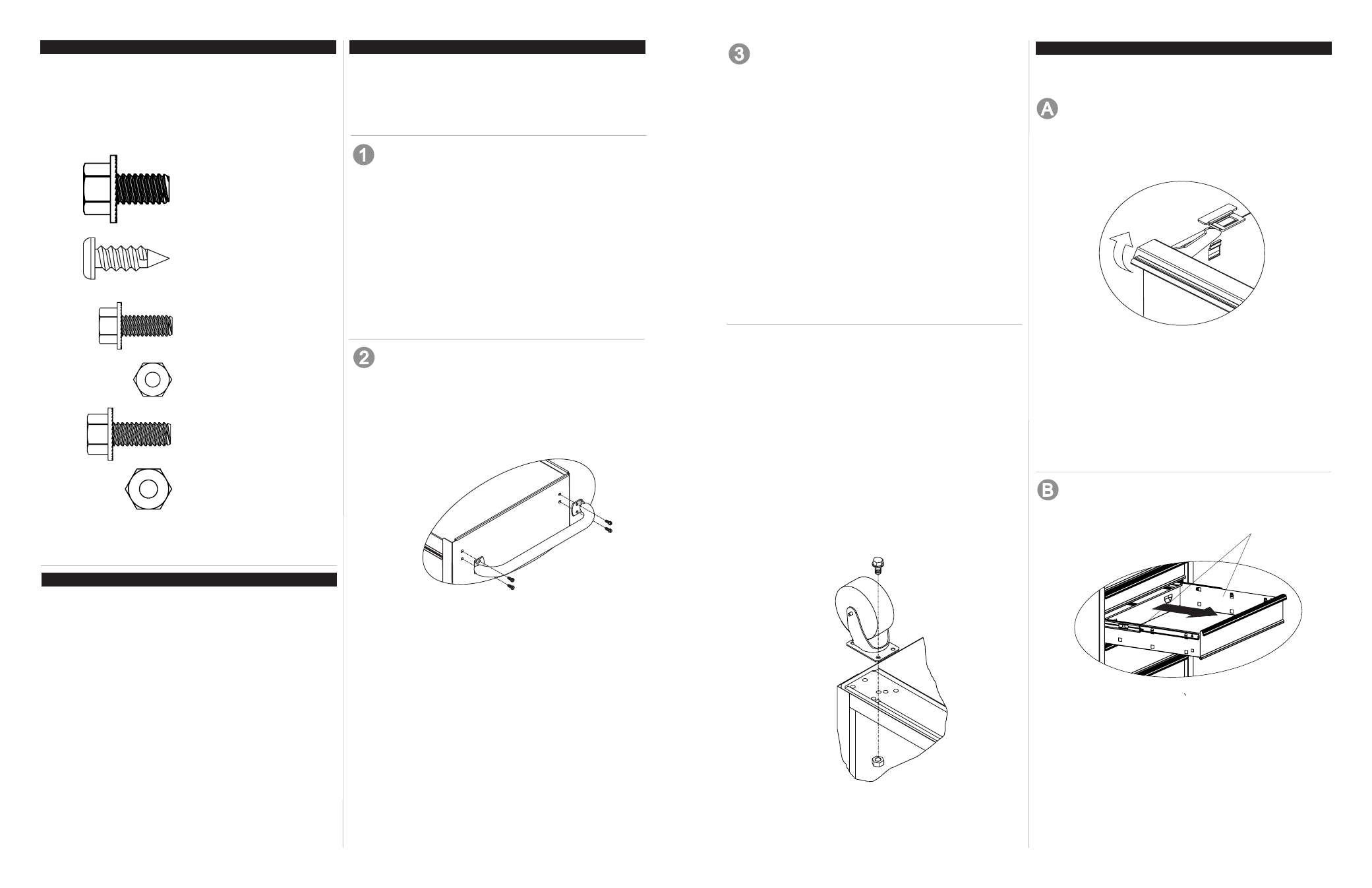
RAISE AND RELEASE DRAWER FRONTS
NOTE: These units are equipped with the raise and
release drawer fronts.
• To open, lift up on the drawer front while pulling towards
you.
• To close, shut the drawer firmly until the latch engages.
• Pull back lightly to see if the drawer is completely closed.
• If the drawer does not stay closed, the striker may be
bent, or the striker rubs against the drawer slides.
• To fix the problem, lightly bend the striker until the drawer
will engage in the slide.
• Unit not shown for clarity.
Release
2
3
HARDWARE
ASSEMBLY
CARTON CONTENTS
OPERATION
#14 - 10 x 3/4 Phillips Screw
(Qty: 4)
5/16 - 18 x 3/4 Screw
(Qty: 16)