Part 2 service, Ix nozzle and pilot – Midco E20BP User Manual
Page 6
and yellow tips for NATURAL gas or with well defined
yellow tips for PROPANE gas.
11.
Check the operation of the burner; start and stop it
several times with the thermostat or operating control.
12.
With the burner running, check the operation of all limit
and associated controls.
13.
PERFORM THE FOLLOWING FINAL ADJUSTMENTS
for combustion and flue gas temperature. Take the flue
gas samples and temperature immediately ahead of the
draft control.
A.
Check the draft control to make sure there is no spillage
of flue products into the room.
B.
Make the final setting of the air shutter by
checking the flue gases with an ORSAT or similar
combustion testing instrument. The carbon monoxide
content should conform to local codes, or, in their
absence to the level specified in the United States or
Canadian Standard reference on the front cover of
this manual; and the carbon dioxide content should
be approximately 9.5% for NATURAL and 12.1% for
PROPANE, or within the limits prescribed by the local
codes.
C.
The flue gas temperature should be above 325¡F but
not exceeding 550¡F. Excessive flue gas temperatures
will result in low efficiencies. Low flue gas temperature
may cause excessive condensation.
14.
FILL OUT THE INSTALLATION ADJUSTMENT DATA
TAG and affix to the burner or converted appliance
.
NOTE: For subsequent normal starting and shut off
procedure, refer to CONSUMER INSTRUCTIONS or
to the instruction plate mounted on the burner.
3600 x Test Dial Size x BTU Value
No. of Seconds for One Rev. Test Dial
Then divide by 1,000 for MBH value.
Example: 3600 x 1 x 1000
20
= 180,000 BTU/Hr. = 18
= BTU/Hr.
7.
With pilot lit, wait one minute; then release Manual Gas
Cock Knob on Combination Valve and turn to ON. If pilot
goes out when knob is released, turn to OFF then PILOT
and repeat purging and pilot lighting instructions detailed
above. Incorrect pilot flame gas pressure may prevent
proper heating of thermocouple causing the pilotstat
safety control to drop out. Refer to Section IX for pilot
adjustment.
8.
Turn operating control to ON or set thermostat above
room temperature. Main flame should come on when the
motor reaches operating speed. If not, refer to Trouble
Chart. To make a preliminary setting of the burner input,
determine the manifold gas pressure required from Table
3 and adjust the combination valve pressure regulator
accordingly. See Section XI.
9.
To determine the firing rate for NATURAL gas:
Accurately time test dial for the number of seconds for
one revolution and use the following formula. All other
gas utilization equipment must be off.
For PROPANE gas, consult your local supplier for method
to determine firing rate.
10.
Readjust the air shutter to provide a quiet, soft flame
-- blue at the burner nozzle with well defined orange
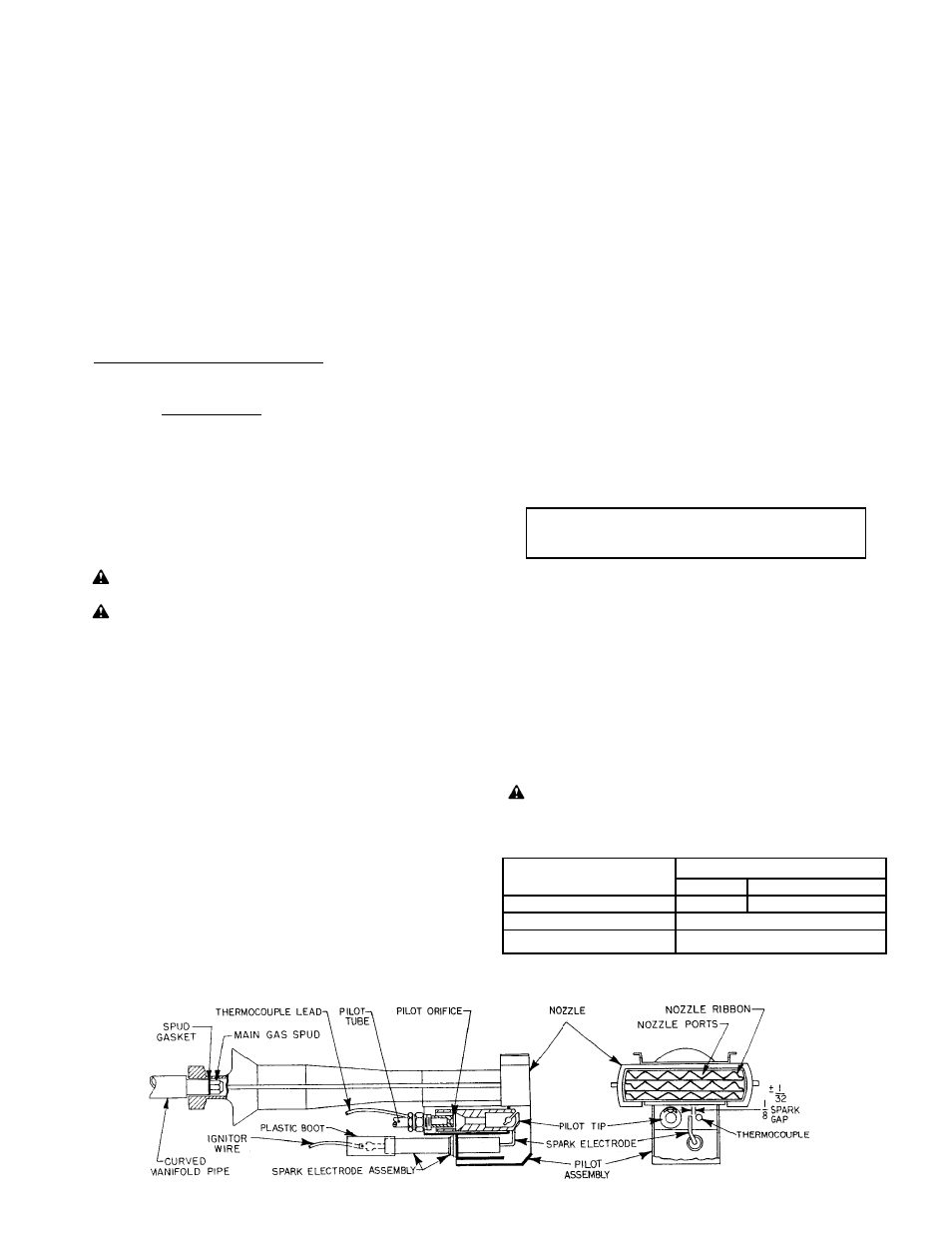
FIGURE 6
Nozzle and Pilot Assembly
-6-
IX
NOZZLE AND PILOT
The nozzle and pilot assembly can be removed as a unit by
removing the back plate, disconnecting the factory installed
union located between combination valve and manifold slide
plate, and pulling out curved manifold pipe. Disconnect
thermocouple and pilot tube at Combination Gas Valve.
Withdraw nozzle assembly, enough to permit disconnecting
ignitor wire before removing nozzle and pilot assembly
completely.
■
When the pilot flame gas pressure is in the proper range,
lint, dust or corrosion is the usual cause for most service
problems. When servicing, clean the nozzle ribbon and pilot
assembly including the pilot orifice and electrode porcelain.
■
If cleaning does not eliminate a pilot outage problem, further
checks are required.
■
Check to verify that the burner nozzle is not installed in too
far. See Figures 1 and 2.
■
A continuous draft is required for the proper operation of the
pilot. This is no problem in the usual up-draft heating
appliance. However, in down-draft or horizontal appliances,
especially during periods of infrequent operation, the available
draft may become nil and result in the pilot products of
combustion being recirculated and snuffing out the pilot.
Excessive draft (over -.05" W.C.) or reverse draft may also
result in nuisance pilot outages. Where a suitable continuous
draft cannot be provided, a spark ignited burner should be
considered.
■
Check that the pilot orifice size is correct (refer to Table 4).
CAUTION:
Do not indiscriminately increase pilot orifice
size. Pilot troubles are rarely cured in this manner and
new troubles may be introduced by causing the pilot flame
to float and lose contact with the thermocouple.
Nominal BTU/Hr. Value
NAT-1000
PROPANE-2500
Orifice Diameter
.018
.012
Pilot Flame Gas Pressure
3.5 - 7.0" W.C.
Approx. Capacity
800 BTU/Hr.
TABLE 4
Pilot Specifications
PART 2
SERVICE
DANGER: Be sure the Main Manual Shut-Off Valve, Combination Valve and Burner Power Switch are
turned off before removing any parts for service.
WARNING: Do not attempt to FIRE the burner with the burner backplate removed as air from the blower
will not reach the combustion chamber and a dangerous level of unburned gas could accumulate.