Part 1 installation – Midco Economite RE6850B User Manual
Page 7
7
The burner gas supply piping should branch off from the main line as close to the gas
meter as possible. Do not connect to the bottom of a horizontal section. Use new black pipe
and malleable fittings free of cutting and threading burrs or defects.
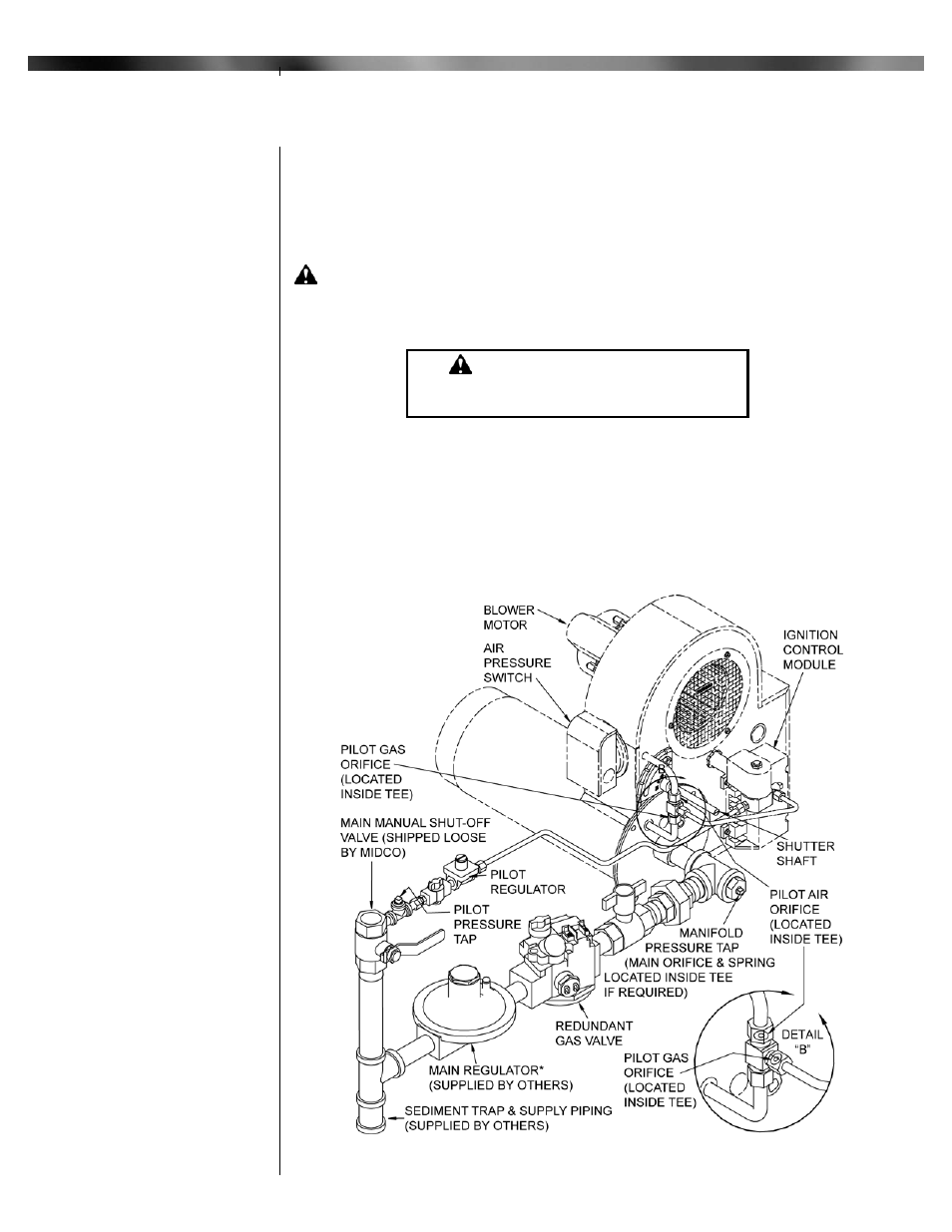
Provide a sediment trap, union and 1/8" pressure tap in piping close to burner as shown in
Figure 5.
Use pipe joint compound approved for use with Liquid Petroleum Gases.
Piping must also comply with your local codes.
To obtain the maximum firing rate of the burner, the gas supply piping must be sized to
provide a minimum of 6.0"W.C. pressure to the inlet of the upstream automatic safety shut-
off valve when the burner and all other gas utilization equipment are on. The pilot regulator
can be mounted in any position, the main regulator, if equipped, should be mounted upright
and in a horizontal run of pipe.
CAUTION: Because it is difficult to accurately control pressure during supply
pipe leak testing, it is recommended that all low pressure (14.0"W.C. max.)
components, both main and pilot, be disconnected during testing. Exposing low
pressure regulators and valves, including manual valves, to pressures over 1/2 PSIG
(14.0"W.C.) will cause damage and void all warranties.
DANGER: Explosion hazard.
Do not use oxygen for pressure testing.
An explosion could occur during initial start up.
If the burner piping must be rearranged because of space limitation, be sure to carry out
the general arrangement shown in Figure 5. Refer to valve and regulator manufacturers
specifications for acceptable mounting orientation.
Run full size pipe or tubing from regulator vent openings to outside of building. Provide no
traps in the vent lines and terminate away from all doors and windows; also make provisions
for keeping rain and foreign objects from entering the vent piping.
When high supply gas pressure is encountered, as in the case in many industrial plants,
the gas line size can be reduced to allow for a greater pressure drop; however, the size must
be sufficient to deliver burner rating pressure.
Part 1 Installation
Figure 5: Piping Diagram for RE6700B - 24V
RE6700B
Valve Train Assembly
24VAC
VI
Piping
Continued
Part 1
Installation
Continued