5 circuit for front flange with air barrier, 6 installing the camera power supply kit – Videotec NXW User Manual
Page 9
EN - English - I
nstruc
tions manual
7
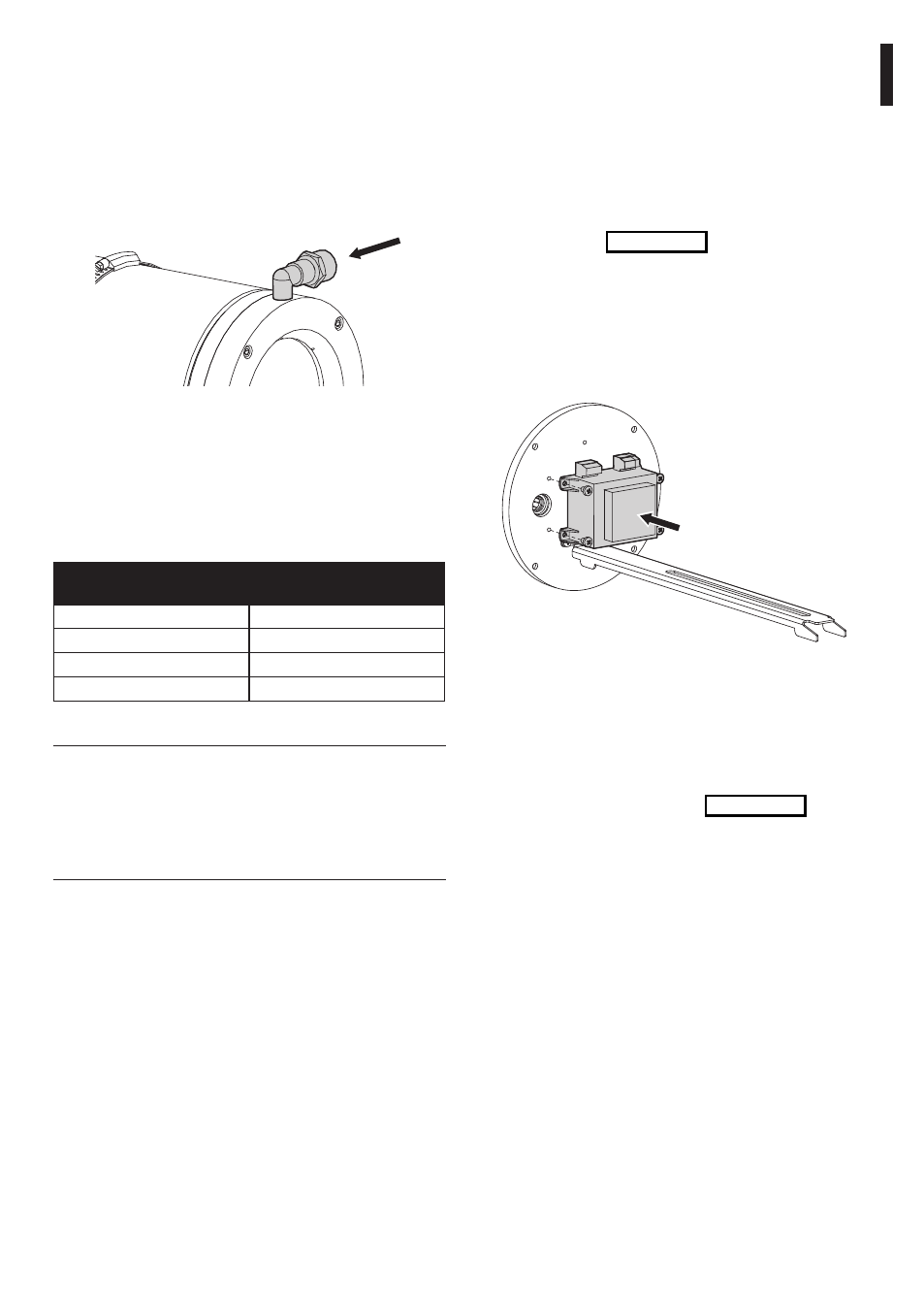
6.1.6 Installing the camera
power supply kit
This section describes how to install the camera
power supply kit inside the housing. It is possible to
install a number of different types of power supply.
The input voltage may be 230Vac or 115Vac while
the output voltage may be 12Vdc or 24Vac, 400mA.
Open the housing following the instructions
given previously (Fig. 04, page 5).
Position the power supply to match the
attachment holes provided on the inner
side of the rear flange of the housing.
Attach the power supply to the rear
plate of the housing using the screws
supplied with the power supply kit.
Fig. 09
Make the power supply-camera
electrical connections.
Close the housing, proceeding in the reverse order
to that described above, making sure the sealing
ring on the rear flange is correctly inserted in its
seating so as not to damage it (Fig. 04, page 5).
6.1.5 Circuit for front
flange with air barrier
This section describes how to connect the housing’s
front flange with air barrier. The air barrier flange
is fitted with a 1/4”Gas threaded connector and
has a 1/2”Gas to 1/4”Gas reduction adapter.
This connector must be connected with the
compressed air circuit supplied by a compressor.
Fig. 08
IN air 1/4“Gas – 1/2“Gas.
We recommend using the optional filter unit
for cleaning the compressed air (NXFIGRU). The
maximum air pressure to be supplied to the air
barrier is 2.5 bar. The following experimental
data give the effective air consumption, for
calculating the size of the compressor:
COMPRESSED AIR
PRESSuRE [bAR]
AIR bARRIER
CONSuMPTION [M3/H]
1
7
1.5
10
2
12
2.5
14
Tab. 02
g
Take care to use the correct camera power
supply kit, according to requirements
(available power supply and required
power supply output voltage). To assemble
the power supply option it is not necessary
to remove any pre-installed component.